

Introduction: Digital Clock Using Arduino and Led Dot Matrix Display


Nowadays, Makers, Developers are preferring Arduino for rapid development of the prototyping of projects. Arduino is an open-source electronics platform based on easy-to-use hardware and software. Arduino has very good user community.
In this project we will see how to build digital clock using Arduino. This project is easy to build and Change it as per the requirement.
Step 1: Components


Following are the required components for project
1 x Arduino Uno
Arduino Uno in India- https://amzn.to/2WmcLHU
Arduino Uno in UK - https://amzn.to/368Cgku
Arduino Uno in USA - https://amzn.to/368Cgku
4 x MAX7219 Led Dot Matrix display
Dot Matrix Display in UK - https://amzn.to/2PuIN3k
Dot Matrix Display in USA - https://amzn.to/2JyDJqF
Dot Matrix Display in India- https://amzn.to/2JHUDTL
1 x DS1307 RTC module
DS1307 RTC Clock in India- https://amzn.to/2WwIl5Q
DS1307 RTC Clock in UK - https://amzn.to/335ID6c
DS1307 RTC Clock in USA - https://amzn.to/335ID6c
Few Wires
Step 2: More About MAX7219

The MAX7219/MAX7221 are compact, serial input/output common-cathode display drivers that interface microprocessors (μPs) to 7-segment numeric LED displays of up to 8 digits, bar-graph displays, or 64 individual LEDs.
Included on-chip are a BCD code-B decoder, multiplex scan circuitry, segment and digit drivers, and an 8x8 static RAM that stores each digit.
Only one external resistor is required to set the segment current for all LEDs. The MAX7221 is compatible with SPI™, QSPI™, and MICROWIRE™, and has slewrate- limited segment drivers to reduce EMI.
A convenient 4-wire serial interface connects to all common μPs. Individual digits may be addressed and updated without rewriting the entire display.
The MAX7219/MAX7221 also allow the user to select code- B decoding or no-decode for each digit.
Step 3: More About DS1307
The DS1307 serial real-time clock (RTC) is a lowpower, full binary-coded decimal (BCD) clock/calendar
plus 56 bytes of NV SRAM.
Address and data are transferred serially through an I2C, bidirectional bus.
The clock/calendar provides seconds, minutes, hours, day, date, month, and year information.
The end of the month date is automatically adjusted for months with fewer than 31 days, including corrections for leap year.
The clock operates in either the 24-hour or 12-hour format with AM/PM indicator. The DS1307 has a built-in power-sense circuit that detects power failures and automatically switches to the backup supply. Timekeeping operation continues while the part operates from the backup supply.
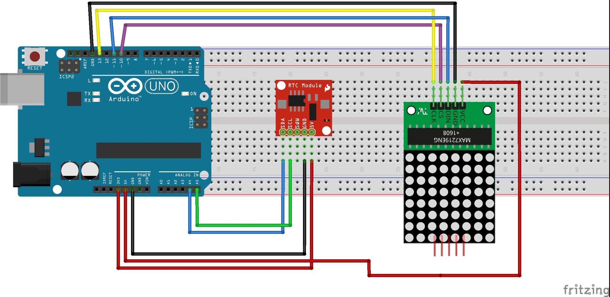
Step 4: Connection Diagram
Step 5: Tutorial
Step 6: Code
For Code and connection details:
https://github.com/stechiez/Arduino/tree/master/di...
You can get the libraries from following repo:


