

Introduction: Digital Window Sticker (Arduino Controlled)


A bumper-sticker sized L.E.D. matrix that displays images in sequence from an SD card, to produce an animated sign or "window sticker." Arduino controlled! Also includes Windows, Mac, and Linux code for converting .xbm image files into Digital Window Sticker files. Perfect for a shop or home window, or a fun desktop sign!
Step 1: Parts List


Digital Window Sticker Parts List
1x | Arduino Compatible Bare Bones Board KIT (BBBKit) Ask for the LM7805 regulator! | $15.00 |
1x | Optional, see below… | $12.00 |
2x | SEE IMPORTANT NOTE BELOW | $11.64 (23.28) |
1x | See PCB note below | $2.99 |
1x | $6.99 | |
1x | $0.09 | |
1x | $0.75 | |
1x | $1.75 | |
1x | $0.32 | |
1x | $0.19 | |
1x | $0.11 | |
1x | See Header Receptacle note below. | $0.75 |
1x | $0.49 | |
1x | See SD-MMC Card note below. | $17.95 |
8x |
$3.98 | |
1x | Low Capacity SD Card (e.g. 512 MB) | |
1x | 9-volt power source | |
Solder and 22-gauge wire of various colors |
The BBB Kit is an Arduino clone produced by moderndevice.com. At $15.00 for a complete Arduino kit, it is one of the least expensive options. I could have cut a few dollars off of the cost by using an alternate Arduino board and a separate supply list for each Arduino component, but the convenience of a single supplier for the Arduino portion of this project was worth the $3 to $5 I may have saved. You should be able to make this project with any Arduino. It can be prototyped on a breadboard as shown below, with a Boarduino, a Bare Bones Board, or other breadboard adaptable Arduino clones. You can also purchase the BBB fully assembled for an additional $10. The owner of moderndevice.com is very helpful and will work with you if you run into problems. Download the BBB assembly instructions and follow them carefully. MAKE SURE to request the LM7805 voltage regulator for the board, or purchase one separately and use it in place of the smaller regulator that he ships by default.
The USB BUB Board plugs into the BBB (Arduino). It has the FTDI USB to serial converter needed to program your BBB Arduino. If you have already have an ICSP programmer, or an Arduino with a ZIF socket for programming the Atmega 328p, it is not necessary to purchase the USB BUB, though it is useful if debugging the microcontroller code, through the Arduino IDE's Serial Port Monitor.
IMPORTANT NOTE regarding the 2416 Dot Matrix Displays. As you view my construction photos you will notice that my 2416 Dot Matrix Display boards don't match. One has white (when not powered) L.E.D.s, the other has transparent ones. The transparent set is slightly dimmer than the diffused set. When I contacted Sure Electronics about the problem they agreed to send a replacement board. It arrived just in time to complete this article, and the final photos and introduction video show the matching set. Unfortunately, the new board they sent me uses the dimmer, transparent L.E.D.s. Be sure to let Sure Electronics know that you need a matching set! You may want to order 3 boards just to be safe. Also, the green boards came out recently. I don't have experience with them, but had they been available when I made my purchase I would have used the green. Finally, remember that Sure Electronics is based in China. Plan on waiting a while for your product to arrive, and arrange for someone to sign for the package. The folks there are easy to work with.
PCBs: If you wish to follow the step-by-step instructions I am providing you will need the Radio Shack printed circuit board, and you will need to trim the ends of it to fit properly in the enclosure. This also means you need a right-angle connector on the 2x8 Shrouded Box Header (that the ribbon cable from the displays plugs into). The right-angle connector is required so that the pins can be bent to bridge the breadboard gap on the Radio Shack PCB. If I were to start from scratch, I'd try using one of the following prototype PCBs, which would also allow you to wire-up a straight 2x8 shrouded box header:
- Prototype PCB with 3-holes per pad, pads spaced .1"
- 103RAW Wireless Prototype PCB with copper traces to each pad which then can be cut, preventing the need for (as many) wires
- Create a custom printed circuit board
Jameco*: Each of the items listed above with an asterisk(*) can be purchased from Jameco, but require a minimum order of 10, so if calculating the cost keep this in mind. (It is always good to have extra parts!)
Header Receptacle: The BBB has 18-pins for the power-supply and Arduino pins to plug into a breadboard. Use the 20-pin header receptacle to plug the BBB into your printed circuit board as shown in the following instructions, with the following variations:
- I did not have a 20-pin header receptacle, but I did have 2 8-pin receptacles. This will work fine. It is a tight fight to get them to align properly, but it works. Just make sure to follow the pictures provided. You'll notice that 2 of the BBB pins are left unconnected.
- If you use the 20-pin header receptacle, 2-pins will remain unconnected. Mark your board so that when you plug-in the BBB you know where it goes.
- You could also forgo the breadboard pins on the BBB, and the socket on the secondary PCB, and simply run wires directly to the needed locations. This may provide some flexibility with enclosures.
SD-MMC Card: Wow, this is an over-priced component if there ever was one. It works great! In fact, don't bother with any of the Arduino SD card Shields. They all seem to use a resistor network to drop the signal voltage to the 3.3 volts required by the SD card. This will not work with all SD cards. In fact, my card worked for only a few minutes this way, and when I put it back in the PC I had to format it, and then it never worked again with the Arduino until I used the 74HC4050 for the signal level conversion. I had other cards that didn't work at all without this as well. If you decide to use a different circuit board, and could plan out the fitting in the enclosure better, I would try to solder a much less expensive SD card socket to the board directly, instead of using the costly breakout board. Incidentally, NKC Electronics has the same breakout board listed for much less, but it was unavailable when I last checked. I don't remember if the breakout board includes header pins. You will need 11. A spare set can be ordered from Jameco: http://www.jameco.com/webapp/wcs/stores/servlet/ProductDisplay?langId=-1&storeId=10001&catalogId=10001&productId=53532, for $0.75.
SD Card Addendum: I've commented at length in the comments (below) about alternatives to the relatively expensive SD Card breakout board. In short, the photos below show experiments I've done with spare parts on a breadboard, using the alternatives for the SD Card socket. Please read the comments and related Instructables for more information.
As for the SD card itself, smaller is better! The Arduino code provided works only with a FAT16 filesystem, and only reads files from the root directory. That means you have a limit of 512 image files on the card, and the files are only 100 bytes. A very small card will work fine, and a card larger than 2GB probably will not work at all. There are FAT32 libraries for the ATMega328, but in the time I had, it was more work than it was worth to get it working with the Arduino. (More later.)
Finally, use a variety of wires when wiring the PCB. It will make it easier to trace connections. As you will see, I used red, black, green, yellow, and white. I wish I had more colors.
Regarding the 9-volt power supply: A 9 volt battery will work, but you will have strange problems when it begins to diminish. Once the battery voltage (when tested on a meter) drops below 7 volts your display may light up fine, but there will be insufficient current to power the Arduino and the behavior is somewhat unpredictable. A 9 volt wall-wart works great, and the LM7805 on the BBB should be able to handle a 12-volt input, like that from an auto-adapter. (Please use caution though if you put this in a moving vehicle! You alone are responsible for what happens if you distract other drivers! You might even want to consider wiring up an accelerometer and disable the displays when the unit is in motion. The circuit is yours as is the responsibility. I recommend it for a home Window or Desktop, or shop Window, not a moving vehicle! I love the idea of it as a bumper sticker, but not at the risk of anyone's life or health! In general however this should be much less distracting than most roadside digital signs, and many printed bumper stickers with hard to read text.)
Tools
I used the following tools to complete this project:
- A quality, variable wattage soldering iron
- Wire cutters
- Wire strippers
- A multimeter (helpful for testing)
- A large solder-less breadboard, for testing - you may not need this
- A Dremel, with cutting wheels and drill bits (for making openings in the enclosure case)
- A variable speed drill and various drill bits
- Arduino IDE 0017
- My micro controller code (see Step 3)
- GIMP image editor, or another editor capable of producing .xbm files
- My xbmtodws code, to create image files for the SD card from .xbm files
Step 2: Assemble the BBB Arduino and USB BUB...


Follow the instructions provided by Modern Device to assemble the BBB Arduino.
Instructions:http://moderndevice.com/Docs/BBB_RevE_Instructions03.pdf
When assembling the BBB, remember to use an LM7805 voltage regulator in place of the L4931CZ50LDO. The smaller voltage regulator might work just fine, but we are pulling quite a bit of current to power up to 768 L.E.D.s. The optional inductor is not needed for this project. You can follow the instructions on creating a solder bridge if you'd prefer to save the inductor, or if you'd rather not deal with the surface mount component. Nevertheless, it is not difficult to solder and I used it on my board.
If you also purchased the USB-BUB follow the assembly instructions to complete it.
Instructions:http://moderndevice.com/Docs/BUB_instructions.02.pdf
When assembling the USB-BUB, I selected Configuration 2, though in practice I only ever use Configuration 1 (no jumper).
Step 3: Program Your Arduino...


BBB Jumpers:
Set the USB|EXT jumper on your BBB to the USB side so that we can program it using the USB-BUB without supplying an external power-supply. (Or, supply a 9 volt power supply on the D.C. input jack and keep the jumper on the EXT side.) When this step is completed you want to move the jumper back to the EXT side!
The other jumper with +5v|EXT|+V should be on the +5v side always.
FAT16 Library Installation:
Next, download the FAT16 library and the DigitalWindowSticker.pde file below. The FAT16 library needs to be unzipped/untared into the hardware/libraries directory where your Arduino IDE is located. On my Windows system, I keep the current version of the Arduino IDE in c:\temp\arduino-0017\. Once the FAT16 library is in place there should be a set of files in [c:\temp\arduino-0017\\hardware\libraries\Fat16\. The FAT16 library is also available here: http://code.google.com/p/fat16lib/. It is written by Bill Grieman. A copy of this library that is known to work with the Digital Window Sticker is available in the files below (Fat16.tar.gz or Fat16.zip).
Arduino IDE:
Start the Arduino IDE.
Open the DigitalWindowSticker.pde file using the IDE. There are two ways you can do this:
1) Download and open the file in a text editor, copy the contents to the clipboard, paste the contents into a new sketch in the Arduino IDE, and then save the sketch as DigitalWindowSticker.
2) Download the DigitalWindowSticker.zip or DigitalWindowSticker.tar.gz file and extract the files to the directory containing your sketches. Then open the DigitalWindowSticker sketch in the Arduino IDE.
Next, compile the sketch. If there are any errors, make sure you are using version 0017 of the Arduino IDE, with the Atmega328 board selected (Arduino Duemilanove or Nano w/Atmega328). Also make sure you've properly unpacked the FAT16 library, into the hardware/libraries directory, where other Arduino libraries reside.
Program the Arduino:
Plug-in the USB-BUB, and wait for for the drivers to be installed, or coach your system into loading the drivers. In the Arduino IDE, a new COM port should show up under Tools|Serial Port. Select the new port for the USB-BUB.
Plug the USB-BUB into the BBB as shown in the photo in Step 2, and Upload the compiled code from the Arduino IDE.
Prepare for External Power Source:
Now that the Arduino is programmed, move the BBB jumper back to the EXT side (not the USB side) so that it will be powered by the external 9 volt source.

Step 4: Assemble the SD-MMC Card Breakout Board


Alternatives:
- Uses wires to connect the SD-MMC card breakout board directly to the printed circuit board in the next step. Doing so will give you flexibility with where the SD card socket is located in your enclosure.
- Solder a bare SD card socket to your selected printed circuit board as part of the next step.
Only the following pins are used:
- CS (for SPI access to the SD Card)
- DI (data input for SPI access to the SD Card)
- VCC is the 3.3v power source for the card
- GND is the common ground
- DO is the data output, which can be connected directly to pin 12 of the Arduino
- WP is used to detect a missing card. This will be connected to pin 2 of the Arduino
- COM needs to be connected to GND
Step 5: Build the Circuit


About the Circuit:
The 74HC4050 is used to convert 5-volt signals sent from the Arduino to the 3.3 volts required by the SD card. There are 6 buffers on the 74HC4050, only three are used by this circuit. All inputs come from the Arduino, and the outputs go to the SD card. The forth SPI connection runs directly from DO on the SD card to Arduino digital pin 12. (The Arduino can read the lower voltage signals just fine.)
Some Arduino projects that use SD cards use a resistor network to drop the 5-volt signal to 3.3 volts. For me this didn't work well. I found one SD card that worked and several that did not. As soon as I hooked up the 74HC4050 all of my SD cards worked.
The SD card has an SPI mode. We connect it to the Arduino SPI pins 10, 11, 12, and 13 through the 74HC4050.
The LM3940IT is a "1A Low Dropout Regulator for 5v to 3.3v Conversion". It takes the 5-volt input from the BBB Arduino board and produces a steady 3.3v that powers both the 74HC4050 and the SD card. Before starting I recommend marking the input pin on the LM3940 to distinguish it from the output pin while building the circuit. The ground pin is in the middle.
The other "component" on the board is the shrouded box header used to connect the LED Display Matrices to the Arduino. The 5-volt power from the BBB Arduino needs to be connected to the displays and to the input on the LM3940. As you will see below, we use the power rail on the circuit board to carry ground on one side, and 3.3 volts on the other. We will directly connect the BBB's 5 volt pin to the LM3940 and the shrouded box header for the LED displays.
Prepration:
Start by laying out the components on the circuit board. If you intend to use the enclosure I've used, in the way I've used it, try to follow the layout in the photos below. It doesn't have to be exact as long as all of the right connections are made, and nothing is connected that shouldn't be. Be careful in planning where the DC jack and the header pins for the USB-BUB on the BBB, as well as the SD card socket will be physically located. This will be important when you place it in the case. If you use the same holes in the PCB that I used, you can get the same match, but beware that it took a fair amount of grinding and cutting to get it to work with the plastic enclosure. Again, it works great, but clearly demonstrates that I am new to the Dremel.
After placing the parts on the printed circuit board, use a thin point Sharpie to mark the pin numbers/labels for the BBB connection and the pin numbers for the shrouded box header. If you don't know where pin 1 is on the box header, attach a ribbon cable into the box header and a solid wire into the other end of the ribbon cable where the red wire lines up and use your meter to test for continuity. You may also want to plug the ribbon cable into the LED display and check continuity between what you think is pin 1 on the box header, and what you think is pin 2, pin 15, and pin 16. Then mark it on the PCB. On top of the LED display are the pins from the shrouded box header soldered to it, one on each side. This makes it very easy to match up your box header pins to those on the display.
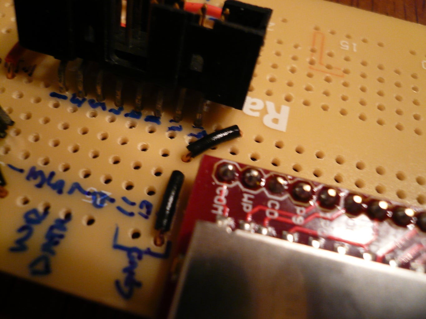
One important note: The shrouded box header I used has right angle connectors. The printed circuit board doesn't have a way of allowing connections to each pin, because on each side of the board the pads are connected like they would be on a breadboard. To solve I bent the pins of the right-angle box header so that one row pins would fit on each side of the breadboard gap on the board. A photo below shows the bent pins. The header sits on the board at angle, but it works great. Be careful not to use too much force inserting it into the PCB -- don't use insertion force to get a better fit, or you run the risk of snapping the PCB in half (voice of experience).
Solder the Components:
Once you have things laid out on the board and have marked pin numbers it is time to solder each of the main components. I recommend the following order:
- The 16-pin DIP socket for the 74HC4050
- The LM3940IT
- The capacitors need for the 3.3 volt regulator (see next section below)
- The SD card breakout board
- The shrouded box header
- The header pin receptacles for connecting the BBB
I elected to keep the capacitors for the 3.3 volt regulator as near as possible to the LM3940. I use two 33µF capacitors between the ground pin and the output pin. One is tantalum capacitor, the other is electrolytic. To save cost, the tantalum capacitor does not require a high voltage rating. 6-volts is just under twice what should ever come out of the regulator and should suffice. REMEMBER that both the electrolytic and the tantalum capacitors are polarized! The long pin needs go into a pad connected to the output of the LM3940, and the short pin into a pad connected to the ground (middle pin) of the LM3940. The leads are small enough that you can fit both in a single hole for each pin.
A .47µF tantalum capacitor goes between the ground pin (middle pin) on the LM3940 and its input pin. This capacitor is also polarized. Be sure the short pin goes into a pad connected to ground and the long pin into a pad connected to the +5v input pin.
The voltage regulator part of the circuit is now ready to be tied to power rails.
Placing the Wires:
Now comes the tedious part: running all of the wires. The more colors of wire you have the easier this will be. Try to keep the wires as direct and short as possible, and flat against the board to avoid clutter and enhance visual traceability.
Power rails:
Start by wiring all of the power connections. I selected the rail behind the LM3940 for the 3.3-volt power line, and the rail on the other side of the board as ground. Run one wire from the output pin of the LM3940 to the rail behind it. Run another wire from the ground pin (middle pin) to the rail on the opposite side of the board.
Next connect the +5v input of the LM3940 to a pad connected to pin 12, 14, or 16 of the box header, and from another pad connected to that line of the box header, run a wire to the +5v line that will come from the BBB Arduino. Pin 16 on the box header is used for +5v in the photos below. This will complete the voltage regulator portion of the circuit.
Now connect a black wire from pin 11, 13, or 15 of the box header to the ground rail. Also connect the ground pin from the BBB to the ground rail. Pin 15 of the box header is used for GND in the photos below. This will complete the power connections for the LED displays and the sources from the BBB circuit.
Connect pin 15 of the box header to the COM pin on the SD-MMC card breakout board, and then connect the COM pin of the breakout board to pin 8 on the 16-pin DIP socket. Also connect the GND pin of the SD-MMC card breakout board to the COM pin of the breakout board. All connections to ground should now be complete.
To complete the power rails, connect pin 1 of the 16-pin DIP for the 74HC4050 to the 3.3 volt power rail. Also connect the Vcc pin of the SD-MMC breakout board to the 3.3 volt power rail.
Wire-up the LED Displays to the Arduino:
Connect the following box header pins to Arduino (BBB) pins:
- Pin 2 of the box header (CS2) to Digital Pin 5 on the Arduino BBB receptacle
- Pin 1 of the box header (CS1) to Digital Pin 4 on the Arduino BBB receptacle
- Pin 5 of the box header (WR) to Digital Pin 6 on the Arduino BBB receptacle
- Pin 7 of the box header (DATA) to Digital Pin 7 on the Arduino BBB receptacle
Wire-up the SD-MMC card to the 74HC4050 and the Arduino:
First the easy one... Connect the DO pin of the SD-MMC breakout board to Digital Pin 12 on the Arduino.
Next connect Pin 7 of the 16-pin DIP for the 74HC4050 (3A) to Digital Pin 13 on the Arduino BBB receptacle. Then connect pin 6 of the 74HC4050 (3Y) to the CLK pin on the SD-MMC card.
Now connect Pin 9 of the 16-pin DIP for the 74HC4050 (4A) to Digital Pin 11 on the Arduino BBB receptacle. Then connect pin 10 of the 74HC4050 (4Y) to the DI pin on the SD-MMC card.
Finally, connect Pin 11 of the 16-pin DIP for the 74HC4050 (5A) to Digital Pin 10 on the Arduino BBB receptacle. Then connect pin 12 of the 74HC4050 (5Y) to the CS pin on the SD-MMC card.
Don't forget to insert the 74HC4050 into the DIP socket as shown in the photo below.
This completes the wiring needed to read files from the SD Card.
Hookup the Card Detect:
In order to be able to tell if a card is present in the SD socket, connect the CD pin on the SD-MMC breakout board to Arduino Digital Pin 2.
Connect the BBB to the header receptacle:
To finish the circuit connect the BBB to the header receptacle. Be sure to align the pins so that they match the labels on our circuit board! After the enclosure is properly prepared we will connect the ribbon cable from the LED displays, completing the circuit!
Attachments
Step 6: The Enclosure


Hack the Board:
Start by scoring each end of the Radio Shack Printed Circuit Board (well away from any copper traces), and use a pair of pliers to break away the unneeded side. When you are done, the board should fit lengthwise against the 6-inch side of the enclosure.
Preping the LED Matrix Displays:
Each of the Display boards has a DIP-switch that controls whether or not the board responds to CS1, CS2, CS3, or CS4. Make sure the board on the left side of the display (when it is facing outwards) has CS1 turned on, and all other switches off. Make sure the right-board has CS2 turned on, with all other switches turned off.
Hack the Enclosure - Lid:
The lid of the enclosure is used to hold the LED displays together. To do this, you need to cut a whole in the lid exactly the length and width of the two displays together. I cut up a cardboard box exactly the size of the two LED displays, not counting the circuit board they are mounted to, or the other components on the board -- just the size of the LED cubes. I then placed this on the inside of the lid and taped it in place with masking tape. I used a box knife to repeatedly score the lid along the sides of the cardboard until the cutout was complete. I little bit of follow-up shaving with the box knife provided a nice firm fit for the LED displays, with the rest of the board behind the plastic.
Next I put the LED displays in place and used a drill with a tiny bit (3/64) to drill holes through each of the screw holes on the display boards. (4 per board, 8 total.)
I placed a 4-40 3/4" machine screw in each hole from the top of the lid. On the inside I secured each screw with a 4-40 nut. On the top screws I placed a second nut to provide a buffer equivalent in height to the transistors on the boards.
With this in place, each display was back into the lid, with the screws going through the screw holes, and another nut added to hold the boards in place.
Hack the Enclosure - Inside:
Now use some ingenious method (I used masking tape to mark approximate areas) to make slots on the side of the enclosure where the following items can be accessed:
- The SD card socket
- The DC power jack on the BBB
- The USB-BUB pins for connecting the serial monitor to the BBB (for debugging, reprogramming, and simply because they need to protrude if the SD card is going to be accessible, due to my lack of engineering that part in advance. ;)
I then placed the boards inside the bottom of the enclosure, aligned the DC jack and the SD card socket just where I thought they'd be suffciently accessible, and then used a hot glue gun to glue the board to the bottom of the enclosure. I also added some hot glue around the DC jack to keep pressure off of the header receptacle when inserting the jack. I placed a small amount of hot glue on the bottom of the PCB before placing it in the enclosure and quickly set it in place. I then lined the entire edge of the PCB with hot glue, again, to keep it firmly in place when plugging in the DC jack or SD cards.
Attach the Cable and Lid:
We can now finally attach the ribbon cables that came with the display board. The short cable should connect the two display boards to each other. The longer cable can go into the other header box on either board. (The bus is shared!) The other end of the longer cable should be plugged into the header box on our printed circuit board. Make sure you orient the cable correctly so the notch aligns.
Attach the lid to the enclosure and tighten the 4 corner screws. The Digital Window Sticker is now complete. If you remove the SD card and power the unit with a 9-volt DC supply through the BBB's DC jack, you should see a message on the display telling you to insert an SD card.
If you don't see the message it is time to pull out your multimeter and verify there are no shorts and that each connection is wired correctly according to the schematic.
Congratulations on your new Digital Window Sticker. In the next step you'll see how to place images on the SD card.
Step 7: Creating and Displaying Images


- Your SD card must be formatted with a FAT16 file system. This is the default for most older cards, and cards less than 2 GB.
- FAT16 limits the number of files in the root directory to 512. The micro controller is only programmed to read files from the root directory.
- Files are read from 0.dws to 511.dws, sequentially.
- When the micro controller reaches a file it can't read (say 10.dws after reading 9.dws) it will restart at 0.dws.
- .dws files are bitmap files with the bits ordered in rows. The first eight bits fills the first row of LEDs on the left-hand side of the display. 16-bits are required for one full row, and there are 48 rows. (24-per display board.)
- To create a .dws file, start with an XBM (x-bitmap) file and use my command-line program xbmtodws to convert the file.
Conversion:
After creating the .xbm files you want to display, run them through xbmtodws. Full source code is attached for xbmtodws. It compiles on Windows with Visual Studio 2005, on Mac OS X with g++, and on Linux with g++. There is a build-linux.sh for examples of how to compile on linux, and a build-macos.sh that shows how to build on Mac.
xbmtodws requires Boost 1.40.0 header files. It uses Boost Spirit to parse the .xbm files, and Boost dynamic_bitset to simplify changing the bits from left-to-right, to top-to-bottom.
Pre-compiled versions of xbmtodws are included in the attached files (xbmtodws-1.0.zip and xbmtodws-1.0.tar.gz). The Linux version is in xbmtodws\xbmtodws\linux. The Mac version is in xbmtodws\xbmtodws\macosx. The Windows (32-bit) version is in xbmtodws\release.
xbmtodws creates a 100-byte .dws file from each 16-by-48 pixel .xbm file. 96-bytes are pixel data, and 4 bytes contain time to display the image in milliseconds.
Converting a file called fred.xbm:
Windows: xbmtodws.exe fred.xbm
Linux/Mac: xbmtodws fred.xbm
By default the image will be displayed for 1 second (1000 milliseconds) . To change the display time use the -delay nnnMilliseconds command-line argument. For example, to show the image for 10 seconds use:
xbmtodws.exe fred.xbm -delay 10000
xbmtodws will create a new file called fred.dws. To display this file, copy it to the root directory of the SD card and give it a numeric name with the .dws suffix (e.g. 0.dws). Remember that if you leave a gap in the numbers, say you have files 0.dws, 1.dws, and 3.dws, only files 0 and 1 will display. An error will be detected reading 2.dws and the microcontroller will start again at 0.dws.
Another option is to invert the image. Use the -inverse flag to invert the image when the .dws file is created.
Animations:
It is possible to create animations like those shows in the video on the Intro screen, by creating a sequence of images with small movements between frames and a short delay.
You now have complete instructions to create your own Digital Window Sticker. Please post feedback showing how you use your Digital Window Sticker!
Second Prize in the
Arduino Contest


