

Introduction: Dimming and Brightening an LED With Arduino
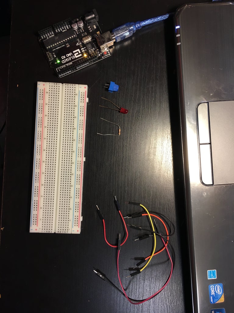


Before you start building, you need to get the right materials:
- 1 Arduino Board - I used a knockoff of an Arduino Uno, but it works the same way.
- 1 Potentiometer - mine looks different than most, but they also work the same way.
- 1 Breadboard
- A few jumper cables
- 1 LED and Resistor - I would recommend the resistor be over 250 ohms for safety.
- A computer with the Arduino IDE installed
Lastly, be careful! You're working with sharp stuff and currents here so take precaution with every step.
Step 1: Hook Up the Arduino Board to Your Computer

Hook up your Arduino to your computer using the USB cable that came along with it. If you haven't already set up your Arduino, connect your Arduino to your computer, and make sure your configurations are right. Under "Tools," select "Port" and make sure you click the one that you connected your Arduino too. Also, make sure under "Tools," you have the right type of Arduino Board selected in "Board."
Once you've done that, take a look at the "Power" pins, "Analog in" pins, and "Digital" pins. Take notice to the squigglies ( "~" ) next to some of the numbers in the "Digital" pins section. These squigglies mean that these pins uses Pulse Width Modulation (PWM), which is just a fancy term that means it can translate analog signals to digital. This will come in handy in later steps, so take note.
Step 2: Giving Power to Your Breadboard

Alright, now that you have everything set up, take two jumper cables, and connect one jumper cable from the "5V" of the "Power" pins section to the column of holes under the "+" sign. Connect another jumper cable from the "GND" of the "Power" pins section to the column of holes under the "-" sign. This will create a power and ground column of holes on your breadboard.
Step 3: Using a Potentiometer

If you already know what a potentiometer is and how it works, you can skip this step. If you don't, I'll explain it here.
A potentiometer has 3 pins. The 2 pins on the left and right are Power and Ground pins, and they are reversible, meaning you can connect 5V to the left pin and GND to the right pin and vice versa and it will still work. The middle pin is the "data" pin. When you turn the potentiometer, the middle pin just outputs the reading.
Step 4: Connecting the Potentiometer
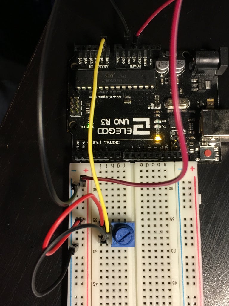
Now that you know what a potentiometer is, let's connect it the breadboard. You'll use it to change the brightness of the LED. Stick your potentiometer on your breadboard. I recommend you insert it to the middle of my breadboard so I would have space to hook up some pins beside it. Connect the left (or right) pin of the potentiometer to the Power column on your breadboard and connect the right (or left) pin of the potentiometer to the Ground column. Now use a jumper cable to connect the "data" pin of your potentiometer to a pin in the "Analog" pins section. I hooked mine up to "A0."
Step 5: The LED

Now that the potentiometer is in, the next step is to connect the LED. Insert the LED onto your breadboard and use a jumper cable to connect a "Digital" pin with a "~" next to it with the longer leg of the LED (don't mix it up with the shorter leg, otherwise it won't work). Now you need to place a resistor to prevent your LED from burning up. Place one end of the resistor on the same row as the shorter leg of your LED, and the other end in the Ground column of your breadboard.
Step 6: Time to Code!

Great! Everything is in place. Time to Code!
In the photo, I have a sample of what I did. Initially, there will be two functions: "void setup()" and "void loop()." If you're new to Arduino, the setup() function is used to "setup" the things you connected to the pins on the Arduino Board. The loop() function is where the real magic happens: it simply loops through the code you write in the function.
The first two lines, I used integer variable "LED" and set it to 6 (6 is the pin I connected the LED on my breadboard to, so if you used a different pin number, set it to that pin number). I also set up the integer variable "potentiometer" to "A0" because that's the pin I hooked up my potentiometer to (again, if you used a different pin, set up your variable to that pin).
In the setup() function, I started the Serial Monitor (I'll discuss that later) and typed "pinMode(LED, OUTPUT)." This statement lets the Arduino know that pin 6 (which equals variable "LED") is an output, meaning it'll be outputting voltages. I don't type "pinMode(potentiometer, INPUT)" because, by default, it is already an input.
In the loop() function, create and set a variable (I used "knob") equal to whatever the input of the potentiometer reads using the "analogRead( /*your name for potentiometer pin*/ )" (for me it was analogRead(potentiometer)). Then "map" the variable. What does that mean? The potentiometer intakes a value between 1 and 1024, and it needs to be between 1 to 255 for your LED to brighten and dim properly. The "map" function divides up the potentiometer into equal intervals of 1/255, which will come in handy when programming the LED.
This next part is optional, but using the Serial Monitor, you can see the value the potentiometer outputs. If you started the Serial monitor under the setup() function and asked it to print a variable in the loop() function (I did "Serial.println(knob)" which let me monitor the value of knob), when you start the program and click on the magnifying glass icon in the top right corner, there will be a giant list of numbers that will be constantly be updating. Those numbers will be the current value of your potentiometer as you turn it.
Finally, write the value of the potentiometer (which I stored in variable "knob") to the LED by typing "analogWrite( /*whatever you named your LED variable*/, /*whatever you named your potentiometer variable*/ )" (in my case, I typed "analogWrite(LED, potentiometer)").
Compile and upload the code and play with your dimmable LED!
Step 7: Enjoy!
Congrats! You did it!


