

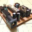
Introduction: Dual BCD to Hex 7-Segment Driver


I one day found myself needing to display a binary value in Hexadecimal. The project was centered around an 8-bit Microprocessor. I needed to view the values of it's Address and Data busses as I stepped through programs.
Unfortunately, there are not, to my knowledge, any currently manufactured logic ICs to achieve this. Knowing that there were examples of both Lattice and Atmel PLDs being used as Hex drivers, I decided to start there. However, I immediately hit a setback. The first problem was that all examples would only drive a single digit display. Since I needed six digits, this would increase my chip count. The second problem was that each of these older devices are quite power hungry, often to the tune of 100mA. Just displaying the six digits could consume over half of an Amp!
So, I set out to find a way to display two digits with one GAL22V10. And the project was quite interesting. The biggest problem I encountered was that the internal Macro Cells just didn't have enough room for the combinational logic equations that I wrote using OpalJr. Figuring that it was quite outdated, I decided to learn another descriptive language and tried my hand at WinCUPL, available from Atmel.
Designed with Atmel variants in mind, WinCUPL has a better compiler, one that has several minimization settings. This would be crucial in getting the description to fit. And the JEDECs compiled are compatible with Lattice Devices.
Step 1: The GAL22V10

The GAL22V10 is a Programmable Logic Device commonly sold under the Lattice name. There are also Atmel variants called the ATF22V10. This device is not entirely unlike an EPROM or EEPROM, with several distinct differences. First, many of the pins are programmable as either Inputs or Outputs. I won't touch on the internal architecture other than in a very simplistic way.
The 22V10 has a total of 22 I/0 pins, of which 10 can be used as outputs. Each one of these output pins has it's own OLMC, or Output Logic Macrocell. These Macrocells can be programmed to be Active High, or Active Low, output. Internal to the Macrocells there are several features, including: a Flip-Flop, a 4-to-1 MUX, and a 2-to-1 MUX for input. Each Macrocell may be configured as either Combinational or Registered Logic. This allows the device to be used for very complex operations.
Each Input of the device is connected to a complex AND / OR array, which handles much of the combinational logic functions. Combined with the Macrocell, this allows for some pretty neat tricks. If you'd like to read the datasheet, the link is below.
Step 2: The Software and Source

WinCUPL is available from the Atmel website. They, at the time of writing this instructable, offer this software with a free lifetime license. Here is a link for the software request, which requires a valid email address for the download link.
The software is Windows based, as the name suggests, and I have encountered very few issues using the software on my Windows 10 system. Once you figure out how to set the compiler for minimization with any given project, the software, and simulator, seem to run fine. One thing to note is that while the software was designed for Atmel products, the JEDEC files produced programmed my Lattice PLDs without issue.
The source I have written, along with the compiled JEDEC files for both a Dual Hex driver and a Single Hex Driver for the GAL16V8 are being hosted at SourceForge. This seemed to be the logical place to archive this code. There will be a link to this Instructable from that page, which is located below:
Step 3: Programming Your PLDs

To program PLDs you'll need some type of programmer. I personally own half a dozen or so. However, the only one that I own that is of any use in this area is one of my cheaper programmers: the TL866CS (aka, MiniPro) Programmer. Being available from the popular online auctions sites for as little as $35US, I cannot stress how incredible of a deal this little programmer is. Initially I had problems with the software and PLDs. But that seems to be corrected as of v6.50. And offers support for the GAL16V8, GAL20V8, GAL22V10 and the ATF16V8, along with the variations of the Lattice products. However, I'd almost be willing to bet that one brand would work with the other. Though, I can not verify this.
Either way, if you need a cheap programmer that offers a lot of value, this is the one to get. And I highly recommend it. But my guess is, that if you're reading this, you may already have a programmer. So checking to see if it supports PLDs is the way to go.
Step 4: Wiring the Device


One thing to note is that this driver is designed for a Common Cathode display. Although if you needed a Common Anode driver, the source is easy to edit, and self explanatory. If enough requests are made I may rewrite and include a Common Anode variant of the JEDEC.
Another consideration is that this driver requires a TTL clock signal. The speed isn't critical, anything from a few kilohertz to megahertz should work fine. But it does need to be a fairly clean square wave. I have noticed that higher frequencies tend to cause partial illumination on unlit segments. I am assuming this to be the result of the limitations of the device itself. It does has a propagation delay of around 4ns.
Aside from that, pin 1 is the clock, pin two through 9 are inputs D7-D0. Pin 24 is VCC, Pin 12 is GND, and the outputs are pins 15-23, with pins 15 and 23 being active low to sink current from the ground pins of the displays.
The theory of operations is simple. The data lines are connected to pins 2-9, the clock to pin 1, and the outputs to pins 16-22 according to the pinout of your display. Pin 23 is connected to the ground pin of the high nibble, Pin 15 is connected to the low nibble's ground pin. When the clock signal is LOW, the data from the High Nibble is converted from BCD to Hex, and displayed on the first Display. When the clock signal is HIGH the data from the Low Nibble is converted from BCD and displayed on the second Display. And that's really all there is to it. There is no blanking supported. So if a value is zero, it is going to show a '0'.
Step 5: GAL16V8 Hex Driver

In the event that you would like to have a Hex Driver for a 7-Segment display, but you do not have any GAL22V10s, you can use a GAL16V8 as a driver. However, it will only drive one display. There are several examples of this, listed as examples in several software packages. However, this is my own spin on this device. The source, and the JEDEC, are located in the Zip file hosted on SourceForge. The download link is listed above.
The wiring for this is very simple. Pin 2-5 are D3-D0, Pins 13-19 are the output pins. And pin 10 is Ground, will Pin 20 is VCC. Unlike the Dual driver using the 22V10, the Ground pin of the Display does not need to be connected to the PLD. Instead just connect it with a resistor to Ground. I find that a 1K resistor works just fine, and provides ample brightness. But I have also used a large as a 10K without any problems. Again, this design has no blanking pins, so a zero will show a '0'.
Step 6: Final Thoughts
I had been thinking about this project for several months, but I had a hard time figuring out how to go about the software design process. I understood combinational logic equations. But all my efforts were simply kicked back by the compiler with an error saying I had exceeded the available space in the OLMC. After reading the WinCUPL manual it became apparent that I could simplify my equations, and use minimization settings to decrease the size of the description. Resulting in the entire project coming to fruit within less than a day from the time of picking up a new syntax.
I am giving this to the greater web as an open source project. I'm sure there are others like me who want/wanted something similar to this at one time or another. It may be expanded to offer other designs at a later time, but that really depends on the reception it gets from the greater community.
If you have any thoughts of the project, I'd love to hear your input. Feel free to drop a comment below.


