

Introduction: Wired Remote Control Without Batteries


More by the author:


About: Send me a message if you're interested in Technology or Science Workshops in Flanders, Brussels or the Southern of the Netherlands. I have over 20 years of experience in developing and giving creative workshop…
This Dynamo Rover is a wired remote control toy that does not require any batteries, but uses the renewable energy source of kids’ muscle power (or the muscle power of adults addressing their inner child).
The idea of using a dynamo or generator to power a toy can be found in products like 4M’s Dynamo Robot. What I did is adding a basic mechanism for steering control and working out a simple way to build the complete rover out of two hacked servos, three wheels and just a few extra parts.
This little project demonstrates how a hacked servo with a crank becomes a pocket-sized generator. As servos are based on a DC motor, simply reversing the direction in which you rotate the crank reverses polarity and gives you forwards and backwards movement on the rover.
Inspired by toys from the times that remote control largely relied on mechanical solutions, I made the backwards movement into a steering action. By making one wheel run forwards only and cleverly positioning the other wheels, you can still go straight forwards, but moving backwards becomes turning, almost on the spot. This way you can get anywhere you want (al be it not in the fastest way).
Here's a video of the Dynamo Rover in action:
The very basic mechanism is based on the use of a spoked wheel and a simple “catch” with tape as a hinge. Here is a video in close-up:
If you can pick up two cheap servos, the cost of this project is pretty low. The wheels and the few extra parts shouldn’t set you back more than couple EUR/USD.
I'm planning on making a version with laser cut chassis, wheels and "catch", somewhat more expensive, but even simpler to assemble. I'm thinking of giving it a scorpion look, with the tail holding up the wire and the front wheels integrated in the fangs.
If you like this Ible, please give it your vote.
Step 1: What You Need


Parts:
2 standard servos, the cheapest you can get are suitable
1 servo horn screw (to keep the horn on the servo output shaft)
4 servo mounting screws (the ones that usually come with a servo are suitable)
2 rubber grommets and brass inserts as common to mount servos in models susceptible to vibrations.
15 cm (6") of threaded rod with a diameter suitable as free running axle for the wheels (M4 or 8-32 with the wheels mentioned above)
10 nuts fitting the threaded rod
a 4.5 cm x 3 cm (1 3/4" by 1 3/16") piece of plywood or another stiff material that can easily be trimmed
a little duct-tape
a 200 mm (8") tie-wrap
your choice of decoration materials (keep it light). I used Play Corn. For some more information on Play Corn, see here)
Tools:
a soldering iron and a little solder for electronics (desoldering gear can help, but is not really needed for the simple desoldering in this project)
sturdy cutting pliers
2 wrenches fitting the nuts (7 mm size for M4, and if I read the info on the net right: 11/32 wrench size for 8-32)
a Phillips screwdriver fitting the screws on the servo (size PH0 or close)
a saw
a metal file
for gluing the play corn: a damp piece of cloth on a plate
Important for safety:
a sturdy work surface, not minding scratches
safety goggles/glasses
some clear plastic sheet
2 standard servos, the cheapest you can get are suitable
I used these from Modelcraft, which look to be the same as the Tower Hobbies STD TS-53.
If you happen to have a servo with fried electronics but sound motor and gears, you can use it for this project.
If you want to use smaller servos, you can, but then the cheaper ones tend to be not strong enough to serve as dynamo.
2 servo horns (normally come with the servos)1 servo horn screw (to keep the horn on the servo output shaft)
4 servo mounting screws (the ones that usually come with a servo are suitable)
2 rubber grommets and brass inserts as common to mount servos in models susceptible to vibrations.
The cheapest servos often do not come with the latter two those. You can buy them separately (like this set) or use other screws about 2.5 mm x 20 mm and a short tube loosely fitting those)
1m25 (4') of twin cable the more flexible, the better, you only need thin gauge. I used 2 wires from 0.08 mm2 (28 AWG) servo cable.
You can use two single wires too, and even glue them together at intervals with some superglue (I recommend not to glue them together over all of their length, as this adds stiffness).
3 wheels 4 to 6 cm (1 5/8" to 2 3/8") diameter, of wich at least one has spokes on the inside. I used these from Opitec and alternatively these and these. They all work, but the first (the biggest) give the best speed. You can find these very same at Kelvin too, be it at a rzther high price.15 cm (6") of threaded rod with a diameter suitable as free running axle for the wheels (M4 or 8-32 with the wheels mentioned above)
10 nuts fitting the threaded rod
a 4.5 cm x 3 cm (1 3/4" by 1 3/16") piece of plywood or another stiff material that can easily be trimmed
a little duct-tape
a 200 mm (8") tie-wrap
your choice of decoration materials (keep it light). I used Play Corn. For some more information on Play Corn, see here)
Tools:
a soldering iron and a little solder for electronics (desoldering gear can help, but is not really needed for the simple desoldering in this project)
sturdy cutting pliers
2 wrenches fitting the nuts (7 mm size for M4, and if I read the info on the net right: 11/32 wrench size for 8-32)
a Phillips screwdriver fitting the screws on the servo (size PH0 or close)
a saw
a metal file
for gluing the play corn: a damp piece of cloth on a plate
Important for safety:
a sturdy work surface, not minding scratches
safety goggles/glasses
some clear plastic sheet
Step 2: Hacking the Servos


Hacking servos for continuous rotation has become a classic. You can already find quite a number of Ibles on how to do that; like this one. The way to reconnect the motors for this project is described in the next step. However I first added a step on the hacking itself, to contribute with my own humble tips and tricks on the topic.
The tab on the output shaft hindering continuous rotation, is easily cut with pliers. With the servos I used, this does not need any further trimming or sanding for smooth continuous rotation.
For this project the electronics are completely removed, as described in the Ible mentioned above and in this one specifically on that. I found it easiest to completely remove the circuit board with motor and potentiometer. First I pushed in the potentiometer shaft and then pulled out circuit board, potentiometer and motor all together. I did not use desoldering braid or a desoldering pump to desolder the motor. Instead, while melting the solder on one motor tab, I pulled out this side of the motor. Then I did the other tab. On one of the motors I had to redo the first tab to free it from the circuit board. I put the motor back in the servo casing without gluing as the original glue still kept it from turning.
Step 3: Reconnecting the Motors


Both servos are hacked in exactly the same way. Before closing up each of the servos again, the motors are soldered each to one end of the twin cable as shown. The polarity (which motor tab is connected to which one on the other motor) does not matter as reversibility is built into the concept. When both servos are connected and closed up, check temporarily put on horns to check if turning the shaft on one servo, powers the other one to turn (should work both ways).
Note: the servo electronics can be reused as a low power reversible ESC, like in this project.
Note: the servo electronics can be reused as a low power reversible ESC, like in this project.
Step 4: Front Axle and Wheels


The rover is built around one of the two hacked servos. The wheels are arranged in a triangle, with the powered wheel in the middle-back. This configuration combines a good movement forwards with a good turning when driving backwards.
A simple way to mount the two front wheels is using a threaded rod. This threaded rod is put in one of the servo’s mounting holes and kept in place by tightening two nuts together, one on each side of the servo’s mounting flange. The end towards the bottom of the servo should be cm long, the other end about cm. On each end put a nut and counter nut leaving about 2cm free. Nut and counter nut means tightening the nuts against each other, fixing them in place. Put on two wheels on the axle, with the spokes towards the inside. The wheels are kept in place with another nut and counter, making sure they run freely with a minimum of sideways movement. If not all your wheels have spokes, make sure the one at the bottom side of the servo has.
A simple way to mount the two front wheels is using a threaded rod. This threaded rod is put in one of the servo’s mounting holes and kept in place by tightening two nuts together, one on each side of the servo’s mounting flange. The end towards the bottom of the servo should be cm long, the other end about cm. On each end put a nut and counter nut leaving about 2cm free. Nut and counter nut means tightening the nuts against each other, fixing them in place. Put on two wheels on the axle, with the spokes towards the inside. The wheels are kept in place with another nut and counter, making sure they run freely with a minimum of sideways movement. If not all your wheels have spokes, make sure the one at the bottom side of the servo has.
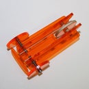
Step 5: The Steering Mechanism


The steering is based on locking one front wheel when driving backwards. The body of the servo serves as a base for a simple “catch” on the nearest wheel. Some tape serves as a hinge.
Cut the piece of plywood (or other stiff sheet material) to a right-angled triangle with a 3 cm base and a 6.5 cm height. Tape it on the servo as shown.
Cut the piece of plywood (or other stiff sheet material) to a right-angled triangle with a 3 cm base and a 6.5 cm height. Tape it on the servo as shown.
Step 6: The Powered Third Wheel


The third wheel goes on the output shaft of the servo. The rubber wheels I used were a direct fit. I only had to replace the fixing screw with a longer one. For this I used a third servo mounting screw.
Step 7: The Crank


The other hacked servo just needs a crank to turn it into a small power generator. There are several ways to make a crank for the servo to be serving as a dynamo. It is obvious to start from a servo horn. I choose to make it completely out of parts that come with servos anyway.
One servo horn will be mounted on the servo as it is originally intended. But first the other one is used to lengthen lever arm. The screws normally used to mount the servo into a model, can be used in the holes of the horns, be it screw them in needs some force. Screw two of them into the two outermost holes until they just start peeking out at the other side. Be careful when putting force on them. Work on a sturdy working surface.
Align the screws with the two outer holes of the other horn and screw the horns together, letting the screws pass through a couple of mm. Wearing safety goggles, cut of the screw ends on both sides, using safety goggles. Covering your work with some clear plastic avoids going looking for the sharp pieces cut of where they might fly off.
It is important to file of the sharp ends or cover them with some tape, in order not to hurt anyone using the dynamo.
Put two of the rubber grommets onto a third screw and put it in the farthest hole of the lever arm. Try and avoid it peeking through too much. File off the sharp end of the screw.
Mount the extended horn assembly on the servo and keep it in place with the screw accompanying the servo for this purpose. Here, the tip is not be covered with tape, so the it should be filed down thoroughly.
Test turning the crank to see the other servo’s output shaft turn.
Step 8: Trimming


The working of the catch only just lock the wheel when moving backwards, and freely move upwards when moving forwards. It will probably need some trimming. You can either shorten the catch or move the wheel by loosening the middle nuts on the threaded rod and tightening them again with the wheel at the right position relative to the catch.
You can also trim to improve the rover running straight forward. Repositioning the front wheel without the catch the relative position of the front wheels and the powered wheel can be changed. The speed at which you run the rover will affect its running straight. With the powered wheel slightly to the right, the main tendency will be a slight deviation to the left, which is good, as this is easily corrected by turning right when moving backwards.
You can also trim to improve the rover running straight forward. Repositioning the front wheel without the catch the relative position of the front wheels and the powered wheel can be changed. The speed at which you run the rover will affect its running straight. With the powered wheel slightly to the right, the main tendency will be a slight deviation to the left, which is good, as this is easily corrected by turning right when moving backwards.
Step 9: Finishing


To keep the wires from getting entangled in the wheels, they should be attached well on top. You can integrate this in the way as a very simple basis I made an arch with a tie-wrap as shown and knotted the wires to its highest point.
I made a robot torso out of Play Corn because it works fast and is light. I attached it to the front axle and the tie-wrap with some tape, making sure it doesn't hinder the wheels or the steering mechanism.
I made a robot torso out of Play Corn because it works fast and is light. I attached it to the front axle and the tie-wrap with some tape, making sure it doesn't hinder the wheels or the steering mechanism.

Participated in the
Green Tech Contest

Participated in the
Wheels Challenge

Participated in the
Remote Control Challenge

Participated in the
Hurricane Lasers Contest


