

Introduction: ESP8266 Home Automation Part 1


Everybody heard about Home automation. It's an interesting theme and many thought about making the home a bit smarter. In this instructable i show you my way to make your home smarter and some advice to realise it. I work with the popular ESP8266 Node-MCU v0.9 (ESP-12 Modul). It's not essential to work with this modul but ist has many advantages. On the one hand it's easy to program with the Aruino IDE and his micro usb port so you don't need a FTDI Programmer on the other hand it has many ports for sensors.
In this instructable i describe the essentials of Home automation like temperature, humidity, light monitoring and connecting wall socket to switch lights On/Off.
Step 1: Parts and Tools


Parts:
- ESP8266 Node-MCU v0.9 dev. kit
- enamelled copper wire 0,5mm
- old smartphone charger (not less than 1000mA)
- dotted perfboard
- Male and Female Pin Header
- old IDE flatcable (not really necessary, i made male to female jumper wires)
- DHT11 sensor for temperature and humidity
- Light Dependent Resistor (LDR)
- Resistor for LDR (100K)
- LED (colour of your choice)
- Resistor for LED (470 ohm)
- RF 433 MHZ receiver / transmitter
- MAX7219 eight 7 segment display
This list is for the voltage doubler. It's absolutely not necessary but you can extend the range of your RF 433MHZ transmitter.
Voltage doubler
- NE555 (1x)
- Diode 1N4004 (2x)
- capacitor 4,7 uF (2x)
- capacitor 100nF (1x)
- capacitor 1nF (1x)
- resistor 39 kohm (1x)
Tools:
- soldering iron
- solder
- pliers
- saw
- drill (5mm)
Step 2: "Mainboard"


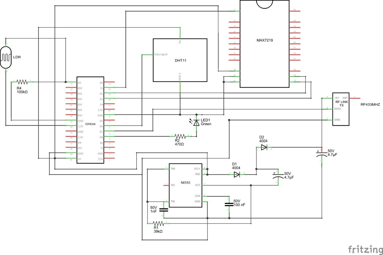


This step is for the "mainboard". Place your ESP8266 on your PCB and let enough space around for two rows female header on both sides of your ESP8266 (picture1) and the sensors. My PCB is 7,5 x 5 cm big.
Unfortunately i made the pictures after soldering so i haven't an step by step soldering instruction (pictur 2). A hint is to start with the small parts. The third picture shows you the entire circuit. If you don't want the voltage doubler circuit you can connect the ESP8266 directly with the RF 433MHZ modul. Picture four is the bottom of the mainboard. Last picture is a pinout diagram of the ESP8266.
Step 3: RF 433MHZ Modul


In this step we work with the RF 433MHZ receiver module to find out the modulation on which the wall sockets and the remote communicate. The first picture shows the connection between an arduino nano and the receiver module. It works with any arduino or your ESP8266. You have to install the RCSwitch library and open in the Aruino IDE under "Examples" -> "RCSwitch" -> "ReceiveDemo_Advanced". Compile and upload it to your board and open the Serial Monitor (picture 4). Now you push each button on your wall-socket remote. For each button you will see the code of your remote. The interesting part is the decimal, bit length and the pulselength. You will need these three information of each button later for the Home automation code.
Attachments

Step 4: Range Extension


One option to extend the range of your RF 433MHZ transmitter module is to roll a coil. You need a 5 millimeter drill, enamelled copper wire and a ruler. Take a piece of copper wire and make 17 turns around the drill. Pull the coil carefully of the drill. The coil should be 20 mm long, if not pull or push it a bit for the right length. Now solder the antenna on your transmitter module. The second picture shows the module after soldering. Nice, first step for range extension done.
Step 5: Voltage Doubler


This is the second step for range extension. If you are satisfied with the range of your RF 433MHZ transmitter module you can skip this step.
The voltage doubler is made out of a NE555, two diodes, 4 capacitor and one resistor. It's a pretty simple circuit for extending the range. The first picture shows the circuit of the voltage doubler and the transmitter. Input pin 8 and 4 will be connected to the 5V supply voltage of the ESP8266 board. The output is nearly 10 V. The transmitter works in range of 3V - 12V and the higher the voltage is, the higher is the range of the transmitter. The second picture shows the circuit on a little piece of perfboard. I made this circuit afterwards i finished my mainboard. But you can solder the voltage doubler directly on the mainboard.
Step 6: MAX7219 Eight 7-segment Display


The MAX7219 eight 7-segment display is an easy way to show data on the segment. The module communicates over SPI. You only need 5 pins including voltage supply of your board instead of hundreds and hundreds of pins like multiplexing. I made male to female jumpercables out of an old hdd flatcable and male and female headers. For first application install the "LedControl" library and test your display with the "LCDemo7Segment". With this sketch you can check if the display works correctly and get some suggestions your the code.
Attachments
Step 7: The Code
At first you need to install the following libraries: "blynk_library", "ESP8266WiFi" and "SimpleTimer".
If it's done you can start with the sketch.
The following adjustments you have to do:
Codeline 33: The input pins of your board for the 7-segment display
Codeline 50: the char auth, in the brackets you fill your token given by the blynk app (later more)
Codeline 69: Here you put your SSID and the password of your router
Codeline 71: You have to write the pulselength of your wall socket remote
Codeline 134: This is the part where you write the other information of your wall socket remote.
These are the important modification to run the sketch for the first time.
Step 8: Blynk App Installation and Setup


Blynk is for android and iphone. I show you the way for android and i think it's very similar for iphone. At first you open Google play and search for blynk and install it.When you open the app it looks like in the second picture. You have to push on "Create New Project". The next screen shows the options for Project Name and the list of boards which blynk supports. Choose ESP8266. You have to write the Auth Token from the app in your sketch in line 50. That's important otherwise the app can't find your ESP8266 board. After the setup you have an empty space where you can place your gauges for the sensors. The fourth picture is my setup of the board. At the bottom there are switches for the wall sockets at the top you see the gauges for temperature, humidity and brightness. Picture five and six is the setup for the humidity and switch.
Step 9: The Last Step


If you done all prior step you can put everything together and start your Home automation.
The picture shows my completed board.
If you have questions or problems ask me and i will try to help you.
As the name of the instructable already said this is the first part. I will extend this projection the next days or weeks.
I plan for the second part the integration of the garage door.
If you like my instructable leave a comment and/or like it.
At the end if you really like it please vote for me in the Full Spectrum Laser contest.
Have a nice day.

Participated in the
Full Spectrum Laser Contest 2016


