

Introduction: Seven Pro Tips for ESP8266


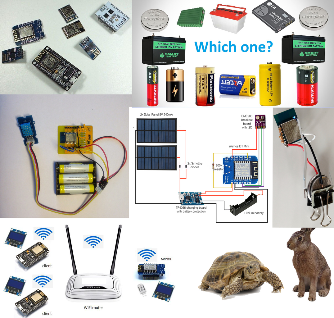


I am sure, every maker and hobbyist are familiar with ESP8266 and I hope you also have some previous hands-on experience with the ESP8266 wifi transceiver. In this Instructable, I am not going to discuss the basic, how to get started etc. You will find tons of tutorials on the internet about these. If you want to develop a professional product using ESP8266 this instructable is for you.
In this instructable I am going to discuss:
1. How to configure wifi credentials on the runtime without hardcoding
2. Which battery technology is best for a specific application
3. Which voltage regulator is best for ESP8266
4. How to run your ESP8266 more than a year using AAA cell
5. How to reduce power consumption of ESP8266
6. How to update your ESP8266 over the year (OTA)
7. How to make you ESP8266 supper fast
Step 1: Configuring Wifi on Runtime (avoid Hard-coding)

There’s no doubt that the ESP8266 has made creating little WiFi widgets pretty easy and inexpensive. However, a lot of projects hard code the access point details into the device.
If you hard-coded values in your sketch, if you change your WiFi router or want to bring your device to somewhere else, you are going to need to re-program your esp8266, which isn't a good idea! This problem is even worse if you plan on a commercial product. It also makes your sketches less shareable.
There’s a better way to do it: using the WiFiManager library. WiFiManager does what a lot of commercial devices do. It initially looks like an access point. You can connect to it using a phone or other WiFi device. Then you can configure it to join your network by setting the network ID, password, etc.
[Witnessmenow] has a good tutorial and a two-minute video (which you can see below).
One image is taken from this nice instructable by Gyalu1.
Step 2: How WiFi Manager Works


- When your ESP starts up, it sets it up in Station mode and tries to connect to a previously saved Access Point
- If this is unsuccessful (or no previous network saved) it moves the ESP into Access Point mode and spins up a DNS and WebServer (default ip 192.168.4.1)
- Using any wifi enabled device with a browser (computer, phone, tablet) connect to the newly created Access Point
- Because of the Captive Portal and the DNS server, you will either get a 'Join to network' type of popup or get any domain you try to access redirected to the configuration portal
- Choose one of the access points scanned, enter a password, click save
- ESP will try to connect. If successful, it relinquishes control back to your app. If not, reconnect to AP and reconfigure.
Step 3: How to Configure
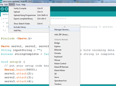

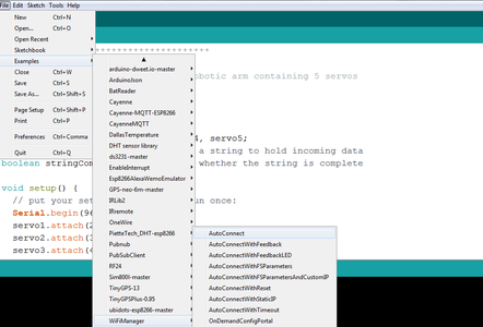
By far the easiest method of installing the WiFi Manager is to use the Arduino Library Manager. In the Arduino IDE go to Sketch > Include Library > Manage Libraries, then in the search bar type "wifimanager". You should see the following:
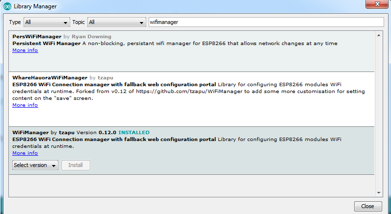
Click install, which will download and install the WiFi Manager library for use. Once installed you can go to the Arduino Library Folder to see the example sketches to upload to your ESP8266 module.
After you have written your sketch and have started the ESP8266, it will then try to connect to WiFi if it has previously successfully connected. Otherwise it will fail to connect and then start up an AP mode. Once in AP mode you can connect to it openly and then in your web browser navigate to the default IP address which is 192.168.4.1, to configure the WiFi, it should then begin to proceed to connect to your WiFi.
You can find out further information regarding the WiFi Manager library from their GitHub page.
Step 4: Choosing a Suitable Battery for ESP8266


Before choosing a battery we need the understand about voltage and current rating of an ESP8266. From the datasheet, we find nominal voltage of the esp8266 is 3.3V. Minimum voltage for stable operation is 2.5V and the maximum allowable limit is 3.6V. So for safely running an ESP8266 device, the battery voltage should be within 2.5 to 3.6V. An esp8266 chip can draw maximum 170mA current. So, for the esp8266 battery discharge rate should not be less than 170mA.
Now, let us discuss the most commonly available battery types used in electronics.
Non-rechargeable type
Zinc-carbon battery: most commonly available and the most inexpensive dry cell primary battery that delivers about 1.5 volts and most common sizes are AA, AAA, and 9V. The 9V type should not use for ESP.
Lithium batteries: dry cell primary battery that delivers about 1.5 volts and most common sizes are AA and AAA. Lithium batteries are also available in coin, and button form with an output voltage 3V.
Alkaline battery: dry cell primary battery that delivers about 1.5 volts and most common sizes are AA, AAA, and 9V.
Rechargeable type
Lithium-ion battery: Lithium-ion is the most common rechargeable battery today and delivers about 3.7 volts. Li-ion battery is available in different size and capacity including AA, AAA, 18650.
Nickel–metal hydride battery: Ni-MH batteries have a nominal output voltage 1.2 volts and most common sizes are AA, AAA.
Nickel-cadmium battery: Ni-Cd has nominal cell voltage 1.2 volts and commonly available sizes includes AA and AAA.
I mentioned the possible battery technology that can be used to power up ESP module. Now, let us analyze one by one. First, consider non-rechargeable AA & AAA size battery because they are most commonly available and inexpensive one. Zinc-carbon and Alkaline type AA and AAA size battery (or cell) have an output voltage 1.5 volts. So, at least two battery with a series connection (to make 3 volts) is required to power up an ESP module because according to data sheet at least 2.5 volts is required to power up an ESP module.
Now, let calculate the run time of two batteries connected in series. If we connect two battery in series the ESP will live until each battery voltage drained to 1.25 volts. From the discharge curve below it is clear that for a zinc-carbon battery about 25% capacity can be used before the voltage reduced to 1.25 volts. So, it can not be a good solution. If we use two Alkaline battery we can use at best 30% which is approximately same as Zinc-carbon battery.
If we use Lithium battery we will get an interesting result. We can get at least 70% energy from a Lithium battery before going cut-off level.

So, in a single sentence, I can say that we should not use two Zinc-carbon or Alkaline cells in series to power up an ESP module if we don't like to keep 75% energy unused in the battery before throwing it. But, we can use a Lithium battery to power up an ESP module. Lithium batteries are most common in button or coin form. A typical Lithium coin cell has the output voltage of 3 volts which is perfect for powering up an ESP module. But before taking the final decision we should consider another important parameter of the battery, maximum discharge capacity or maximum current supply capacity in a simpler term. Most of the coin cell cannot provide more than 20mA! The average current taken by an ESP module is 80mA. So, a standalone coin cell is not enough to provide sufficient current to power up an ESP module. A parallel capacitor can give a good result but required some experimentation to know the exact response.
Now investigate the rechargeable group. The most common rechargeable battery used today is Lithium-Ion battery. Lithium-ion batteries are available in different size and dimension. The output voltage of a Lithium cell is 3.7 volts and capacity depends on the size of the cell.

From the above discharge curve of a Li-ion battery, it is clear that though the nominal voltage of a Li-ion battery is 3.7 volts, a fully charged Li-ion battery voltage starts from 4.2 volts which is more than the tolerable limit of an ESP module. So, Li-ion battery should not directly connect to ESP module.
The output voltage of both Nickel-metal hydride & Nickel-cadmium cell is 1.2 volts. So, if we connect three cell in series than total output voltage will be 3.6 volts which is within the tolerable limit of an ESP module. The open circuit voltage of a fully charged Ni-Cd can be 1.3 volts. So, connecting three we get 3.9 volts which I think will not create any problem in ESP module.
So, three Ni-Cd or Ni-MH cell in series can be connected directly to power up an ESP module.

Now the second question comes. How much energy can we get from the battery? From the above discharge curve, we find that both cells provide their maximum energy before reducing the voltage to 1.1 volts. So, when three cells are connected in series the total voltage is 3.3 volts at the end of the life cycle of the battery and this voltage level is far greater than the minimum level of the ESP module. So using Ni-Cd or Ni-MH battery we can use most of the energy (above 80%) before going to recharge the battery.
Ni-MH battery has greater capacity comparing to Ni-Cd. Other characteristics of Ni-Cd and Ni-MH is almost same. So, three Ni-Cd or Ni-MH cells in series can be a good choice for powering up an ESP module.
From our above discussion, it is clear that we can not use Li-ion cell directly to the ESP module. We should not use two Alkaline or Zinc-Carbon cells in series because we will get only 25-30% usable energy from the battery. So, now the important question is that if I used 3 Alkaline or Zinc-Carbon cell in series what will happen? Let analyze the fact.
The output voltage of three series connected 1.5 volts cells will be 4.5 volts which is far bigger than 3.6 volts the tolerable limit of the ESP module. Is there any way to use it? Yes, a 3.3 volts regulator is the answer to this question. In the next step, I will discuss which regulator is appropriate for an ESP module. So, keep reading.
Step 5: Choosing a Suitable Regulator for ESP8266


When a steady, reliable voltage is needed, voltage regulators are the go-to component. They take an input voltage and create a regulated output voltage regardless of the input voltage at either a fixed voltage level or adjustable voltage level (by selecting the right external components).
This automatic regulation of the output voltage level is handled by various feedback techniques, some as simple as a Zener diode while others include complex feedback topologies that can improve performance, reliability, efficiency, and add other features like boosting output voltage above the input voltage to the voltage regulator.
Among a number of voltage regulators, linear voltage regulators are most common and affordable one. Linear regulators come in a couple of types, are very compact, and used often in low voltage, low power systems.
Switching regulators are much more efficient than linear voltage regulators, but they are harder to work with and more expensive.
Linear Regulators
Linear regulators are available in different voltage and current output. The most commonly used linear regulator by maker and hobbyists is LM78XX series and LM7805 is the most widely used regulator from the series. LM7805 is a 5 volts regulator and is not compatible with ESP8266. We need 3.3 volts regulator for ESP module.
The most commonly used 3.3 volts regulator is AMS1117 (SOT-223) or LM1117 Voltage Regulator. It is designed to automatically maintain a constant 3.3v output voltage and up to 1A output current and can be used with the ESP8266 module. But one disadvantage of these Linear Regulators like the LM78xx series (where XX is the output voltage) is, AMS1117or LM1117 requires about 2V more on Vin than the expected Vout to function. So, if we want to get a stable 3.3 volts output from AMS1117 regulator the input voltage must be 5.5 volts or at least 5 volts.
So, this regulator (AMS1117 including other linear regulators) cannot be used to power up an ESP module from 3 AAA, AA cells (4.5 volts) or one Li-ion cell (3.7 volts) but you can use these regulators if you have 5 volts source. The solution of the problem is an LDO regulator.
Low Drop Out regulator (LDO)
There is one variant of the linear regulator called the Low Drop Out regulator or more commonly LDO. These regulators are designed to operate with an input voltage much closer to the output voltage compared to traditional linear regulators. TLV74133PDBVR (150mA), TPS76733 and LP2985 (150mA) from Texas Instruments (National), LDK320ADU33R (200mA) from STMicroelectronics and MCP1825S33 (500mA) from Microchip are some 3.3 volts LDO. All of these regulators will work in our case but which one should we select? The Quiescent Current and Standby Current will give us the answer.
Quiescent and Ground Current
Quiescent current (IQ) is the current required to power the LDO’s internal circuitry when the external load current is zero. It includes the operating currents of the band-gap reference, error amplifier, output voltage divider, and overcurrent and overtemperature sensing circuits.
Ground current (IGND) is the difference between the input and output currents and necessarily includes the quiescent current. A low ground current maximizes the LDO efficiency.
Standby Current
Standby current is the input current drawn by a regulator when the output voltage is disabled by a shutdown signal.
For a battery operated portable or remote device Ground current and Standby current must be very low (few uA or nA).
From the above-mentioned regulators:
- TPS76733 has rated current 150 mA and Quiescent current 85uA
- LP2985 has rated current 150mA and quiescent current 1uA
- MCP1825S33 has rated current 500mA and Quiescent current 0.1uA mA.
So, all these regulators can be used with ESP to power up from AA or AAA or Li-ion battery. The average current required for ESP module is 80mA. So, 150mA regulator is enough and MCP1825S33 is overrated which may be required extra cost.
Step 6: How to Run an ESP8266 Over a Year Using AA/AAA Battery


Using Wi-Fi is a convenient way to link your newly created IoT device into your existing IoT infrastructure including cloud services but it also has a drawback. Wi-Fi’s demand for power usually makes battery operation impractical for any real deployment. In a normal operating mode, ESP module consumes about 70mA which leads to drain three AAA battery within a few hours. It is very impractical for remote IoT devices.
Nevertheless, it is possible to put the ESP8266 into deep sleep and wake up periodically to activate Wi-Fi and send data only when required. This would suit a scenario in which an IoT sensor sends relatively infrequent one-way traffic (i.e. where real-time control of the device is not needed).
ESP supports three type of sleep modes in which deep sleep mode requires minimum current (20uA). Waking up the ESP from sleep mode takes about 16mA — plus, once awake it takes about 3 seconds to reconnect, precious time at 70mA. However, by using a static IP address it can be pared down to half a second, with one more second to do the actual data transmission (we will show it in next step).

How to calculate runtime?
Before calculating run time we need to understand the capacity of a battery. "Battery capacity" is a measure (typically in Amp-hr) of the charge stored by the battery, and is determined by the mass of active material contained in the battery. The battery capacity represents the maximum amount of energy that can be extracted from the battery under certain specified conditions. However, the actual energy storage capabilities of the battery can vary significantly from the "nominal" rated capacity, as the battery capacity depends strongly on the age and past history of the battery, the charging or discharging regimes of the battery and the temperature.
Units of Battery Capacity: Ampere Hours
The energy stored in a battery, called the battery capacity, is measured in either watt-hours (Wh), kilowatt-hours (kWh), or ampere-hours (Ahr). The most common measure of battery capacity is Ah or mAh, defined as the number of hours for which a battery can provide a current equal to the discharge rate at the nominal voltage of the battery. The unit of Ah is commonly used when working with battery systems as the battery voltage will vary throughout the charging or discharging cycle. The Wh capacity can be approximated from the Ahr capacity by multiplying the AH capacity by the nominal (or, if known, time average) battery voltage. A more accurate approach takes into account the variation of voltage by integrating the AH capacity x V(t) at the time of the charging cycle. For example, a 3.7 volts battery with a capacity of 1000 mAh allows energy storage of approximately 1 Ah x 3.7 V = 3.7 Wh. However, because of the large impact from charging rates or temperatures, for practical or accurate analysis, additional information about the variation of battery capacity are also provided by battery manufacturers.
The amount of current we can really draw (the power capability) from a battery is often limited. For example, a coin cell that is rated for 300 mAh can't actually provide 300m Amp of current for an hour, in fact, it can't even provide 100 mAmp without overextending itself. It's like saying a human has the capability to travel up to 30 miles: of course, running 30 miles is a lot different than walking! Likewise, a 300 mAh coin cell has no problem providing a 1mA for 300 hours but if you try to draw 100mA from it, it'll last a lot less than 3 hours.
Here are some conservative power ratings for good quality alkaline and zinc-carbon batteries available at the local grocery store.
| Battery Type | Size of the Battery | Capacity (mAh) |
| Alkaline | AA | 2400 |
| AAA | 1000 | |
| Zinc-carbon | AA | 700 |
| AAA | 350 |
A calculation
Suppose we have chosen 3 AA type Alkaline battery to power up an ESP8266 module. The capacity of an Alkaline AA battery is 2400mAh. If we connect three battery in series then capacity will remain same without increasing the voltage level to 4.5 volts. For the edge of calculation, we are considering 100% capacity will be used by ESP module.
Typical current consumption of an ESP8266 module in normal operation mode is 70mA.
So, serving hours by the battery = 2400/70 = 34 hours
So, if we run an ESP module continuously in normal mode it will run only for one and a half day.
But, most of the IoT device doesn't require transmitting data continuously. Maybe transferring data two or three times in an hour will be ok. In that case, we can take advantage of the deep sleep mode of the ESP8266. In deep sleep mode, ESP module takes only a few microamps. Lat's recalculate the above scenario by taking data transfer rate 3/hour.
Assume, the ESP8266 module requires total 5s to wake up from sleep mode, connect to the internet and sent the data to the server. So, in an hour it will consume only 3 x 5 x 70 = 1050mAs
So, the battery will serve for(2400 x 3600)mAs / 1050mAs = 8228 hours = 342 days.
This is a very rough calculation. In an actual case, we cannot get 100% energy from a battery and here we don't consider the current in sleep mode. So considering all the practical difficulties it may reduce to about 300 days.
[Some text and images are directly copied from the internet.]
Step 7: Reducing Power Consumption


This part is taken from the blog by Erik H. Bakke. Thanks to Mr. Bakke for is valuable work.
From the power consumption chart below, we see that the WiFi radio switches on as soon as the ESP wakes up. The bootloader runs for about 0.35 seconds, after which it hands over control to the code uploaded to the ESP.
 After that, the next 2.3 seconds are spent connecting to the WiFi access point. This is just establishing an association with the AP, there’s no DHCP or other traffic yet.
Next comes 1.2 seconds of nothing at all happening. Interestingly, this period would be far longer in some cases, ending with the ESP crashing and rebooting with an exception 29.
Next is DHCP traffic. This is how long it took before DHCP packets started appearing in the traffic analyzer. The time taken to acquire a DHCP lease varied greatly, but on average it would take about 3 seconds.The final power peak is the transmission of the sensor readings to the server, before the code sends the ESP into deep sleep.
From the graph, we can see that each time the device wakes up, we spend about 1.5 seconds doing useful work (reading sensors 1.2 seconds, transmitting results 0.3 seconds), out of a total 8.3 seconds the device was awake. The red line shows the accumulated power consumption, rising steadily to a total of 0.164mAh per reporting cycle.
Now, let's see how we can reduce the consumption.
Disabling WiFi when waking up
As the WiFi radio is on when the ESP wakes up, we wake up with 70 mA current even if we’re not using the WiFi yet. To try to reduce this, let’s switch off the WiFi radio at the beginning of the setup() function, keep it off while we’re reading the sensors, and switch it back on when we are ready to send the results to the server.
void setup() {
  WiFi.mode( WIFI_OFF );
  WiFi.forceSleepBegin();
  delay( 1 );
From the experiments, it was found that both WiFi.mode() and WiFi.forceSleepBegin() were required in order to switch off the radio. The forceSleepBegin() call will set the flags and modes necessary, but the radio will not actually switch off until control returns to the ESP ROM. To do that we’re adding a delay( 1 ), but I suppose a yield() would work as well.
Then, just before the calls to establish the WiFi connection, we switch the radio back on:
WiFi.forceSleepWake();
delay( 1 );

// Bring up the WiFi connection
WiFi.mode( WIFI_STA );
WiFi.begin( WLAN_SSID, WLAN_PASSWD );
As above, forceSleepWake() will set the correct flags and modes, but the change will not take effect until control returns to the ESP ROM, so we add a delay( 1 ) call here as well.
Let’s have a look at the result…
 Ah, we can clearly see the radio switching off at the beginning of the sketch and it coming back after the 1.2 seconds it takes to read the sensors.
(Un)fortunately, the DHCP ended up being faster this time, so we can’t look at the total energy usage but will have to calculate how much was saved while the radio was off. The current has dropped from 71 mA to 17 mA, giving us a 54 mA saving. Over 1.2 seconds that gives us 0.018 mAh. Not much, but on the right track.
Using WAKE_RF_DISABLED
There’s still a sharp power peak as the ESP wakes up, and by the time the setup() is called, we will have used 0.008 mAh already.
To avoid this we can go to sleep using the WAKE_RF_DISABLED flag. This configures the chip to keep the radio disabled until told to enable it. So we’ll change the call to ESP.deepSleep:
WiFi.disconnect( true );
delay( 1 );

// WAKE_RF_DISABLED to keep the WiFi radio disabled when we wake up
ESP.deepSleep( SLEEPTIME, WAKE_RF_DISABLED );
The calls to WiFi.disconnect() and delay() are needed in order to ensure the chip goes into proper deep sleep. Without them, the chip usually ends up consuming about 1.2 mA of current while sleeping. This indicates that deep sleep was not achieved and that the chip is in Power Save DTIM3 mode. (0.86 mA according to this, a little bit for the voltage regulator and another little bit for the faint sleep LED.)
 OK, the ESP now wakes up with the radio disabled, it stays disabled until after the sensors have been read and we can collect another 0.006 mAh reduction for a total of 0.024 mAh.
Disabling network persistence
As mentioned before that the ESP8266 will persist the network connection information to flash, and then read this back when it next starts the WiFi function. It does this every time, and from experiments, it was found that this takes at least 1.2 seconds. There are cases where the WiFi function would crash the chip, and the WiFi would never connect.
The chip also does this even when you pass connection information to WiFi.begin(), i.e. even in the case below:WiFi.begin( WLAN_SSID, WLAN_PASSWD );
This will actually load the connection information from flash, promptly ignore it and use the values you specify instead, connect to the WiFi and then finally write your values back to flash.
This starts wearing out the flash memory after a while. Exactly how quickly or slowly will depend on the quality of the flash memory connected to your ESP8266 chip.
The good news is that we can disable or enable this persistence by calling WiFi.persistent(). Our code to enable the WiFi network will then look like this:WiFi.forceSleepWake(); delay( 1 ); // Disable the WiFi persistence. The ESP8266 will not load and save WiFi settings in the flash memory. WiFi.persistent( false ); WiFi.mode( WIFI_STA ); WiFi.begin( WLAN_SSID, WLAN_PASSWD );
Let’s see how this affects the power consumption:
 The cycle has become longer, but on closer inspection of the graph and network packets the main reason for that is that DHCP took longer this time.
What is missing this time, though, is the 1.2 seconds between AP association and the start of DHCP negotiation. That’s 1200 ms at 71 mA, or 0.023 mAh saved. Combined with the 0.024 mAh saved so far, we’ve saved 0.047 mAh in total. And we’ve most likely increased the lifetime of the flash chip as well.
The original post is here.
In the next step, I will discuss Static IP.
Step 8: Static IP for Faster Connection


The connection time can be reduced by setting a static IP in ESP8266 and it reduces power consumption. It is very useful if you use deep sleep. Because of every time ESP wakeup, it takes 5 to 6 secs with DHCP but with static IP it reduced to 2 secs and can save two their of power consumption.
The following code can be used to configure a static IP in an ESP module.
#include <ESP8266WiFi.h>

const char* ssid = "********";
const char* password = "********";

IPAddress staticIP(192,168,1,22);
IPAddress gateway(192,168,1,9);
IPAddress subnet(255,255,255,0);

void setup(void)
{
  Serial.begin(115200);
  Serial.println();

  Serial.printf("Connecting to %s\n", ssid);
  WiFi.begin(ssid, password);
  WiFi.config(staticIP, gateway, subnet);
  while (WiFi.status() != WL_CONNECTED)
  {
    delay(500);
    Serial.print(".");
  }
  Serial.println();
  Serial.print("Connected, IP address: ");
  Serial.println(WiFi.localIP());
}

void loop() {}
Turning off the wifi scanning can also reduce the power consumption. For the details visit ESP8266 WiFi power reduction – Avoiding network scan.
Step 9: Over the Air Update (OTA)


OTA (Over the Air) update is the process of loading the firmware to ESP module using Wi-Fi connection rather than a serial port. Such functionality became extremely useful in case of limited or no physical access to the module.
OTA may be done using:
- Arduino IDE
- Web Browser
- HTTP Server
Arduino IDE option is intended primarily for software development phase. The two other options would be more useful after deployment, to provide a module with application updates manually with a web browser or automatically using an HTTP server.
In any case, first firmware upload has to be done over a serial port. If OTA routines are correctly implemented in a sketch, then all subsequent uploads may be done over the air.
There is no imposed security on OTA process from being hacked. It is up to the developer to ensure that updates are allowed only from legitimate / trusted source. Once the update is complete, module restarts and new code is executed. A developer should ensure that application running on a module is shut down and restarted in a safe manner. Chapters below provide additional information regarding security and safety of OTA process.
A very good tutorial on OTA is here.

Participated in the
Pro Tips Challenge

Participated in the
Microcontroller Contest


