

Introduction: EZProbe, an EZ430 Based Logic Probe


this is a simple logic probe project based on TI EZ430 dongle. i took advantage of a free offer on a couple of ez430s from TI in september 2010. they are very handy and fun in trying out small code snippets and watch the led blink. they had since been laying around my desk and i have to come up with something for them. and i want to stop people coming up and ask to borrow my "memory stick".
well, this is no memory stick, 16bit MCU w/ multi-channel ADCs, adequate 2K programming memory and runs up to 16Mhz. all packed up with the debugging programming interface board in a nice usb device package.
my main design goal is to limit my intervention to the original ez430. in that i don't want do alter it too much physically and i want to retain it's programming / debugging function for other target board projects. all this while serve additional useful purposes.
this is a linux project, as usual, i had given attention with my best knowledge to make provisions so that it can be built under windows. however i do not have the time and resources to try out everything under windows.
most of my electronics projects are done on very small breadboards and i usually work on tight spaces (kitchen table, half a borrowed desk, etc). there are many instances that i need to check circuit logic levels and i've been using a multimeter (size of a brick) to check things out. it always annoys me as my projects are much smaller than my multimeter and i found it always gets in my way. i need an alternative, a small logic probe will do.
the ez430 is perfect for this task. to begin with, it's already shaped like a probe, i just need to add a nail and some leds. as i mentioned earlier, i want to make this project simple and non-destructive. and i made use of what's available already.
instead of building the project on a pcb / pref-board, i build this on a target msp430f2012 board, employing the 14 pin header thru holes as my prototyping area. this is where the tiny leds goes. i do not want to drill holes on the plastic casing, i don't want to run too many wire nor add additional contact points. all i need is a probe io contact and a button input for function select, plus gnd and vcc. the usb connection looks perfect for this task. i will power the probe via the usb (the programmer circuit will regulate a around 3v potential for me) and use the D+ and D- usb connects for my probe and switch.
since the ez430 is slave / client device, upon initialization, it won't do a thing except a pull-up on D+ (to indicate it's a "hi-speed" usb). i use the floating D- as my probe io and D+ as my tactile button input (i don't even need to setup a pull-up resistor for that, it's already there)
additional information can also be found here.
Step 1: Features and Application

features
* supply from circuit via usb connector
* 3 operating modes rotating between logic read, pulse output, pwm output
* long button press (about 1.5 sec) rotates through the 3 operating modes
* p1.0 original green led as mode indicator, off - probe, on - output, blink - pwm
logic probe
* logic probe red - hi, green - low, none - floating
* logic probe red / green blinks on continuous pulse reads > 100hz
* 4 yellow leds shows detected frequencies in 8 steps, blinking yellows indicate hi-range (i.e. step 5-8)
* shows detected pulse frequencies for 100hz+, 500hz+, 1khz+, 5khz+, 10khz+, 50khz+, 100khz+, 500khz+
* for non-continuous single pulse bursts, the red / green leds stays on and subsequent pulse counts are displayed incrementally on the leds, will count up to 8 pulses
continuous pulse output, frequency setting
* indicated by p1.0 original green led on
* 4 yellow leds shows output pulse frequencies in 9 steps, blinking yellows indicate hi-range (i.e. step 5-8)
* pulse frequencies output for 100hz, 500hz, 1khz, 5khz, 10khz, 50khz, 100khz, 500khz, 1mhz
* short button press rotates the 9 different frequency settings.
continuous pulse output, pwm setting
* indicated by p1.0 original green led blinking
* same as previous operation mode, except pwm values are show (and be setup) instead of frequency
* 4 yellow leds shows output pwm percentages in 9 steps, blinking yellows indicate hi-range (i.e. step 5-8)
* pwm percentages for 0%, 12.5%, 25%, 37.5%, 50%, 62.5%, 75%, 87.5%, 100%
* short button press rotates the 9 different pwm settings.
schematic
the schematic is made up from two parts, in which they are connected via a pair of usb connectors. the left side schematic shows additions to the EZ430 dongle with a F2012 target board. the right side schematic is the logic probe-head and is to be constructed from scratch.
Step 2: Part List and Construction


parts list
* ti ez430-f2013 (use programmer part)
* ti ez430 f2012 target board
* leds 1.2 x 0.8mm, 4 yellow, 1 red, 1 green
* one nail, around 3/4 inch, flat headed
* one tactile button
* cap from 1 gram super-glue (super-glue itself also needed)
* usb type a connector (pc side)
* wires
construction
i am using the msp430f2012 target board instead of the f2013 target board that comes w/ the ez430 dongle only because i have a few of these. if you want to use the orginal f2013 target board, you will have to re-write a very small portion of code that use adc to dectect floating state. the f2013 has a more advance 16 bit adc instead of the 10 bit used i am using in my construction.
you will need to use a fine solder tip and a temperature control soldering iron (or station), i can't imagine one can solder the leds w/ a regular iron. the way i did it is to tin the header pads first, then use a pair of fine tweeters to place the smd leds. after aligning the red and yellow leds, i tin one leg of a 1/8 watt resistor and solder that onto the pcb, one end goes to a common gnd. the green led goes last. it is very tight and you would want to just apply enough solder to stick things together. also flux is a must. use a multi-meter to test your joints.
you will then need to bridge the button wire and the probe wire. i use cat5e cut offs but any high gauge wires will do. as shown in the schematic and the picture, they run from the target board to the usb connector. it would be nice if i can find a small connector so that they can be dis-engaged at will, but this will do for now.
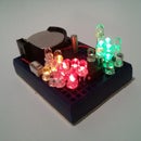
Step 3: Probe Head Construction

at the bottom you will see the bits that i used to "construct" (super-glue) the probe head assembly. my idea is to build it on to a usb connector so that it can be detached for firmware updates. i used super-glue to put everything together. the "nail" is glued directly on top of a tactile button for very quick mode switching and frequency / pwm setting. you may want to do otherwise if it doesn't work for you. there will be some wobbling from the tactile button mechanism, in one design i used paper clip to limit the wobbling and another probe head i used the cap from the super-glue to secure the nail position. you may also want to add protection resistor / diode to it.
the usb connector has these connections, (1) 5v, (2) D-, (3) D+, and (4) Gnd, the D- is to be connected to the nail, the D+ connects to the tactile button, the other end of the tactile button need to be connected to ground.
this probe-on-connector strategy gives me a lot of flexibilities, with power line on the probe head, you can expand the circuit and turn this project into something else by just changing the "head" and firmware, ex. may be a volt meter, a tv-b-gone (w/ transistor and battery on the probe head), etc. i would next add a white led "head-light" to it.
Step 4: Implementation Notes and Alternate Applications

implementation notes
* wdt (watchdog timer) is used to provide button timing (de-bounce and press-n-hold), also to pulse lighting leds. this is needed as leds do not have limiting resistors and cannot be turn on constantly.
* dco clock set at 12mhz to accommodate 3v target circuits.
* adc is used to decide if we probe at a floating pin, threshold values can be adjusted via source code.
* frequency determination is done by setting timer_a to capture for edge detection, and counting the pulse within a period.
* output mode uses timer_a continuous mode, output mode 7 (set/reset), both capture and compare registers (CCR0 and CCR1) to achieve pulse width modulation.
source code
these are instructions for linux only, my environment is ubuntu 10.04, other distros should work as long as you had installed the msp403 toolchain and mspdebug properly.
you can create a directory and place the following files in them
click to download ezprobe.c
i do not have a makefile for this to compile, i use a bash script to compile most of my projects, it is mentioned on my launchpad shield page, scroll down to the section "workspace directory layout" and get the details.
or you can do the following
msp430-gcc -Os -mmcu=msp430x2012 -o ezprobe.elf ezprobe.c
msp430-objdump -DS ezprobe.elf > ezprobe.lst
msp430-objdump -h ezprobe.elf
msp430-size ezprobe.elf
to flash firmware, attach your ez430 dongle and do
mspdebug -d /dev/ttyUSB0 uif "prog ezprobe.elf"
alternate applications possibilities
base on the flexible nature of this design, the ezprobe can easily change it's role and by a quick flash download, becomes a different device, here are some ideas which i intend to implement in the future.
* servo tester, this one i did
click to download ezprobe_servo.c
* battery tester / volt-meter, up to 2.5v, or higher w/ resistor divider on alternate probe-head
* tv-b-gone, w/ ir led probe-head
* pong-clock, w/ 2 resistor tv-out probe-head
troubleshooting
* you really need a temperature control iron / station and fine solder tips, the leds (all together) are smaller than a grain of rice.
* use flux.
* be prepare to disconnect the D- and D+ wires during debugging, they may interfere w/ normal usb operation. if you write firmware on the modified device, do not do output on this two pins when your firmware starts. and if you do, you will no longer be able to download firmware (of course you can un-solder them if this happened). if u can find small connectors that fits into the usb casing, use them.
* power supply for the target board is drawn from the programmer board via a regulator, which in turn takes 5v from usb. when using the ezprobe in circuit, i usually have my target project supply 3v from twin 1.5v AAAs, this is adequate but the project has to stay on or below 12mhz. 16mhz dco will require full 5v source power.
* i did not use limiting resistor or zener diode to protect the probe. you may want to do so.
Participated in the
Epilog Challenge


