

Introduction: Easy Bluetooth Controlled Scrolling Text


Hi all,
In this Instructable, I'll show you how to create a simple scrolling text, using led matrix modules. These modules are cheap and easy to use. And, to make this project more fun, a bluetooth feature was added : you will be able to send a message to the system using a mobile phone !
I'll show you how to wire the system with an arduino card, how the program works, and how to use the device with a smart-phone. If you don't want to use the bluetooth feature, just check the last step to see how to do the same with the arduino serial port.
Follow these simple steps to get a nice gadget !!
Any comments for help, tips, and ideas are welcome !
10k views ! Many thanks !!
Step 1: Stuff Needed


Ok, to create this, you will need :
- an arduino card, with 3v3 logic levels : here, an arduino Nano. You can also use an UNO, but you will have to add a level converter.
- a HC06 bluetooth serial module. Search for "arduino bluetooth serial module" on the web. You will be able to find it easily.
- one or more led matrix modules. You can find them on the web, check "MAX7219 led matrix modules". You can find them ready to sue, or as a kit "ready for soldering".
- breadboard wire, and a breadboard.
- Usb cable for the arduino card.
- (optional) rubbers
- (optional) power supply for the arduino card.
Step 2: Note on the Matrix Modules


Again, these modules are cheap, and easy to find. The great thing about these is that you can wire them in series (8 max), all the boring hardware aspects are handled by the library and the MAX7219 chip.
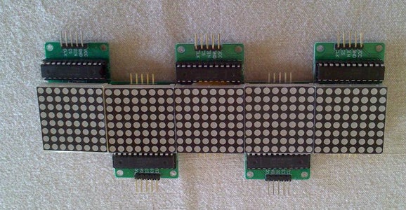
The problem is that you can't directly put them side by side, because of the connectors. You can put them side by side vertically, but the wiring is complicated. (The wires are under the modules...)
The solution is to put them head to tail, like the final picture. You will say "it will not work, as the rows and columns are toggled". Yes, but don't worry, my program handles this, and flip the pixels every two modules, to get a perfect rendering !
My tip : use small rubbers to keep them in contact. Of course, for a nice finishing, you can fix them on a piece of wood, or similar.
Step 3: How It Works
Ok, the program is quite simple :
- the arduino starts. A sample message is displayed on the led matrices.
- if nothing happens on the bluetooth module, the stored message stays on the screens.
- meanwhile, the arduino program check the serial port (where the bluetooth module is connected). If nothing is on the buffer, the same message keeps "turning".
- if some data is available on the virtual serial port, the message is downloaded, and replaces the previous message.
The bluetooth modules acts as a serial client. All the boring connecting/security aspects are handled by the module. In fact, the bluetooth module is connected by two TX/RX signals, and acts as a serial port, just like a computer. A bluetooth client terminal on the phone handles the connection, and allow the user to send and receive text.
Step 4: Wiring the Led Matrices

Ok, the wiring is simple :
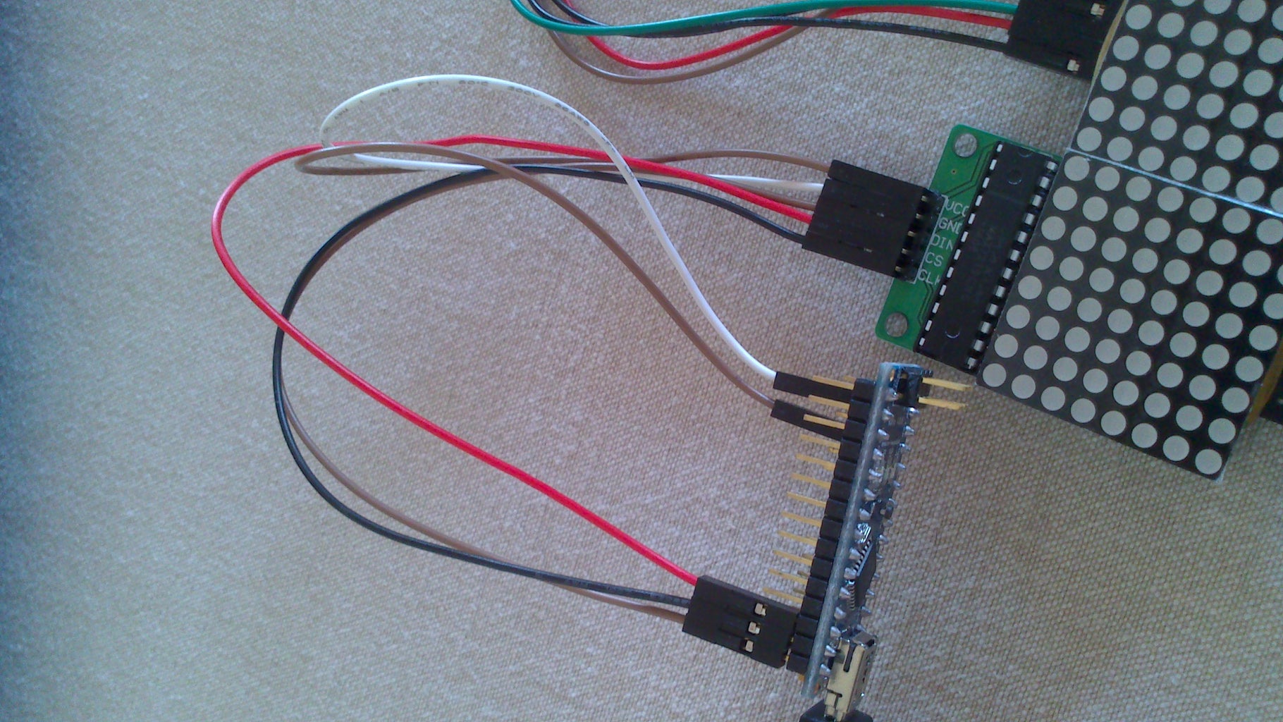
The "input" pins are on the left side of the module, when the MAX7219 chip is on the left.
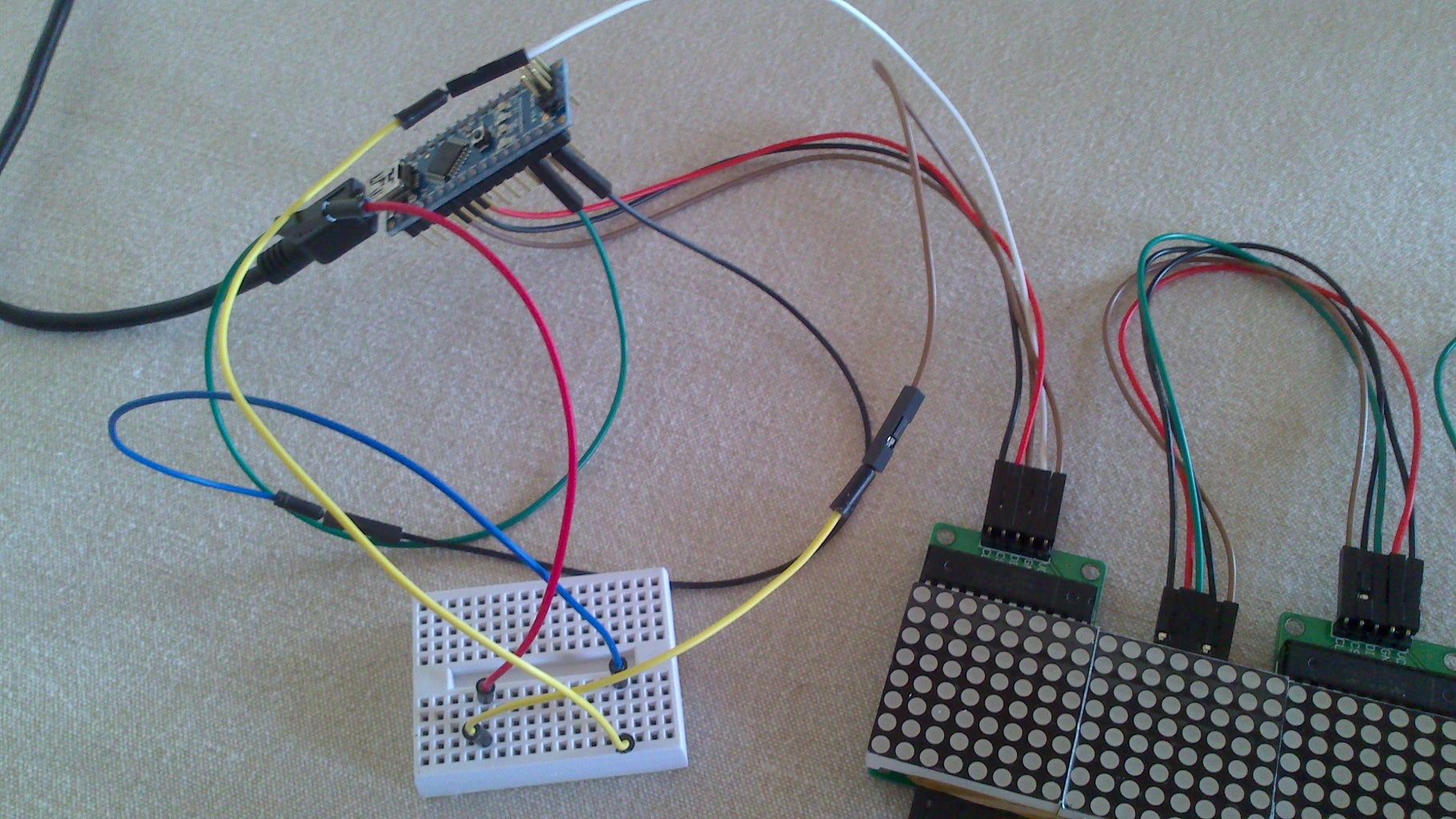
- VCC : on the 5v pin of the arduino. Use the breadboard as you will need more 5v pins.
- GND : Gnd port of the arduino. Again, use the breadboard.
- DIN : pin 12 of the arduino (It's the "Data In" signal of the SPI link)
- CS : pin 10 (the "chip select" signal)
- CLK : pin 11 (the clock signal)
You can put up to 8 modules in series. In my case, I've got 5 of them.
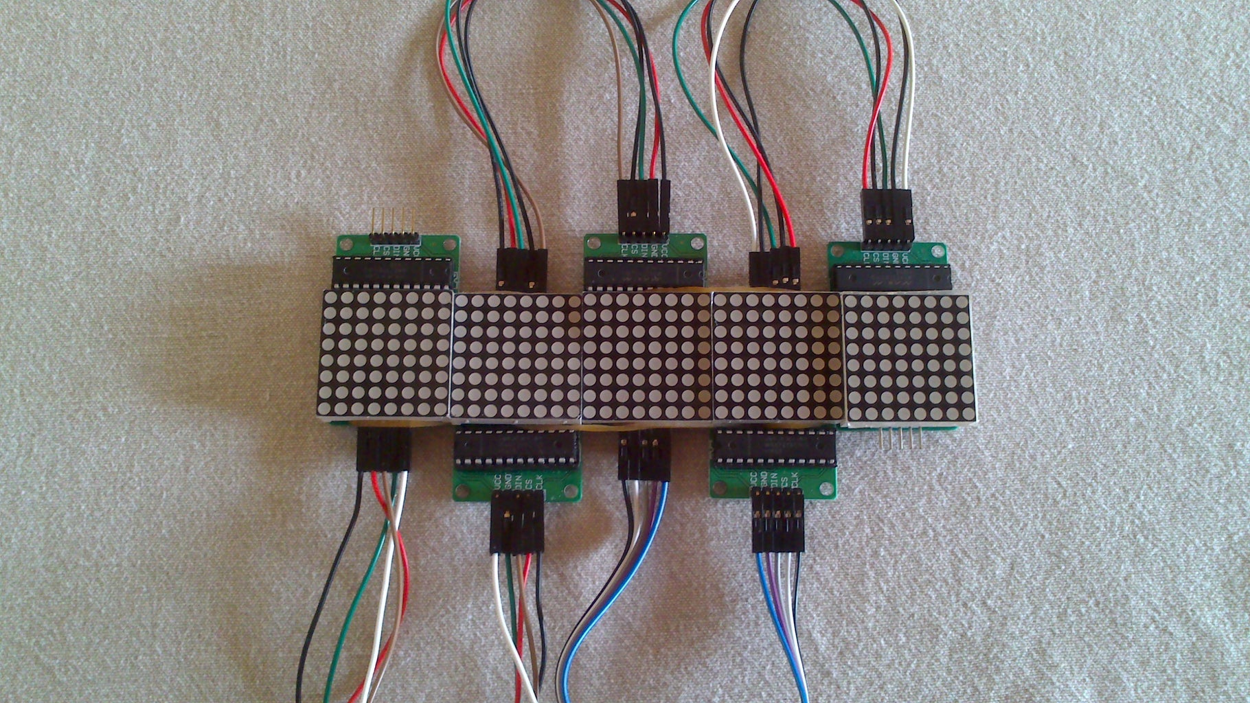
Put the modules head to tail, make sure the input pins of the first module are on the top (check the pictures). Wire them in series, like the pictures. My tip : wire the modules before putting the rubbers, to avoid errors in the wiring.
Use small rubbers to keep the modules together.
Step 5: Wiring the Bluetooth Module

Ok, the bluetooth module is also easy to wire :
- Vcc : 5v pin of the arduino
- GND : ground pin
- Tx : arduino pin 8
- Rx : arduino pin 9
Watch out, the module only handles 3v3 logical levels on TX and RX pins. Don't connect them on a 5v pin ! Use a level converter instead.
When on, a led on the module should blink. In fact, the led blinks when the module starts, then stays ON when the module is connected with the phone. Great for debugging !
My wiring is quite ugly... due to a lack of wires, I had to do something not very good with the breadboard... sorry...!
Step 6: The Program


Ok, the program is attached on this step.
You will need the "Led Control" libraries to compile the sketch. Informations are here.
You can download the libs here (there is a button "download zip" on the right):
Remember, you have to unzip them in the "libraries" folder of the main arduino folder. Make sure the folder name is "LedControl". Make sure that the .H and .CPP files are directly inside.
- Connect the arduino nano to the computer.
- In the arduino IDE, make sure that the correct board is selected (The nano in my case).
- In the program, change the line 40, and put the number of matrices used. 5, in my case. You can use up to 8 modules.
- On the line 48, you can adjust the speed of the text. Put a bigger value if you want to reduce the speed.(It's the delay in ms between a "step" on the screens)
- Compile and upload the program. The modules will blink randomly during the upload process. It's normal !
You should see the welcome message on the led display...

Step 7: On the Phone


Ok, you will have to setup a bluetooth terminal client on your mobile phone.
On the android store, you can find them for free. For this project, I'll use "Bluetooth SPP", but any similar app should work. Just search for "bluetooth serial" or "bluetooth terminal" on the app store.
- Turn on the bluetooth on the phone.
- Use the phone utility to find and locate bluetooth emitters.
- The emitter name is "HC-06". Select Connect. The password is 1234.
- Launch the Bluetooth SPP app. Hit the menu button on your phone, select Connect. Select the HC06 module.
- In the operating mode screen, select Real-time mode.
- The phone will work, then says that the connection is ok.
- Check the bluetooth module, the led should stay ON (no more blinking)
When running again the app, you can use a "Restore last connection" feature to get the connection with the module. Works great !
The app you use may be different, of course.
Step 8: Send a Message !


- Ok, so make sure that the phone is correctly connected to the module.
- Push the reset pin of the arduino.(Optional, but show the initial message)
- Check the phone, you should see "Hi ! I'm waiting for a message. Type it and press SEND."
- Type any message you want, then click on Send.
- The select message should be now on the led display !
Congrats, you make it work !
Step 9: Final Words
Ok, this project is great, because it's based on a very simple modules, and the result is quite useful. You may want to use this as a general-purpose message display... You can finish this project by making an enclosure to hide the wires and make something beautiful...
If you don't want to use the bluetooth, just use the program given here. Use the arduino serial monitor (or other terminal program) to send a message.
I hope my steps are clear... If you need more explanations, just ask !!
Thanks for reading !!


