

Introduction: Easy to Construct/use Transistor Tester


Hello everyone
I got a transistor tester from gearbest.com and because I find it a very usefull tool, I decided to make an instructables about it.
In this instructables, I'm going to show you how to solder the tester together and give all the functions of it.
Let's get started!
Step 1: What's Inside the Package.


First of, I'll talk about what you get inside the package.
When you open the package, you'll see some components including:
- a PCB
- a socket for the test subject (green)
- different type of resistors
- some capacitors
- some transistors
- a microcontroller (Atmega328)
- a crystal for the microcontroller
- a LCD
- a socket for the microcontroller
- a rotary encoder
- and some other small parts.
Basically, you get everything to get started except a 9V battery.
Step 2: Soldering Everything Together


Tip: When soldering a PCB, always solder the lowest components first.
I started with all the resistors. On the PCB there are markings with the value of the resistor. To define the value from the color codes on the resistor, you could use this table.
After the resistors, I added the small capacitors. On the PCB they are marked with the value that you see on the capacitor.
Now I added the crystal.
After the crystal, I added the microcontroller socket. Tip: For easy soldering, bend the 2 outer pins to keep it in place.
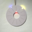
I added the LED after the socket.
Now you can mount the transistors, they are marked with there name on the PCB.
After the transistors, I added the female socket for the LCD.
Now I added the yellow capacitor to the PCB. And I also added the polarized capacitors. The white negative strip comes on the opposite side of the '+' mark on the PCB.
After the capacitors, I added the test clamp, the 9V battery connector and the rotary encoder.
Now last, but not least, you need to add the LCD. Tip: insert the male socket into the female socket, mount the LCD with the spacers and then solder the connections.
Step 3: Some Measurements


I did dome measurements using this kit, and I found it really accurate!
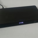
First I tested the frequency generator, from 1Hz to 2MHz. Every frequency was exact what it should be.
It did see that the output at 2MHz wasn't a square wave, but that is normal at 2MHz.
After this I tested the internal frequency meter. I used an oscillator of 1MHz, and it showed exactly the same as my oscilloscope.
The last thing I tested, was the PWM generator. As you could see above, the periods are as I set them.
You can set the percentage of the PWM per percent.
So as you see, this is a pretty accurate meter. I recommend it to anyone for using it. Of course it's not as good as very priced meters, but it does it's job very well.
Note: For using the PWM and frequency generator, you should use the central pin as positive, and one of the other pins as negative.
Step 4: Resume

That's it, connect your 9V battery press on the rotary encoder and enjoy your meter.
The meter can measure many different things.
- A transistor
- Inductance of a coil
- resistance
- capacitance
- PWM
- frequency
- ...
I hope you liked the instructables, please feel free to comment.
If you have any suggestions what you would like to see done, an app, some electronics, something with arduino,...
Please let me know!
Laurens


