

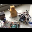
Introduction: Edison Steve - a Quick to Build Robotic Puppet


The above video doesnt play sometimes on mobile devices - here is the link to it on youtube.
This is a fun project that is very easy to build.
I have had to do several demonstrations of electronics to kids new to electronics - and I wanted to let them build something fun themselves; but it had to be something possible to complete in a usually very limited time-frame.
So - the goal of this project was to come up with as low-as-possible part-count robotic-figure that was still great fun to assemble, operate, watch and expand - yet be possible to build in under an hour.
This project then is the result of my continually distilling my various robot designs to come up with the easiest to construct bot that can be put together in under that hour.
This, of course, then leaves it up to the adventurous to expand it further as they wished - light up eyes or an energy sword maybe :)
Note: this Instructable is aimed at Edison Users - if you are an Arduino Fan - there is a more suitable version here.
Step 1: Supplies


Per figure - you will need
- An Edison Arduino Kit
- 1x Breadboard
- 1x Joystick Module (frequently sold from about 0.70c to $3)
- 10x Aprox Breadboard connector wires (a mix of male to male And male to female)
- 1x Lollypop stick (or possibly some stiff cardboard)
- 2x Servo motors
- 1x Pritt Stick or other low mess glue
- 1x Printed out template (see next steps where to get this)
- 10x pieces of double sided spongy pads (box of 100 from local pound shop) (*)
(*) It is Important you use double sided sticky pads - they are able to absorb the motors sudden movements without breaking apart - glue, bluetack, sellotape, duct tape etc are Not a suitable alternative. Try not to touch the sticky parts when affixing as it can reduce their effectiveness.
Some sources for some of the parts: (I'll list all Amazon here - but do shop around keeping postage costs in mind)
Joystick
http://www.amazon.co.uk/KY-023-Joystick-Sensor-Module-Arduino/dp/B00FHRQ2CG
Packet of Two Servo Motors
http://www.amazon.co.uk/Sonline-Servo-Plane-Helicopter-Hitec/dp/B00X9M44YO
Sticky Pads (about 10mm x 20mm)
http://www.amazon.co.uk/Sellotape-Sticky-Fixers-double-12x25mm/dp/B001CN1TR2
Pritt Stick (Glue Stick)
http://www.amazon.co.uk/Pritt-Stick-10g-Pack-6/dp/B000I6QX34
Breadboard cables (its easier if you get both kinds)
http://www.amazon.co.uk/Solderless-Flexible-Breadboard-Jumper-arduino/dp/B00JUDWILM
http://www.amazon.co.uk/Conductor-Female-Jumper-Color-Ribbon-Male-20cm/dp/B00ATMHU52
Step 2: Assemble the Head and Arms


The fun messing with glue step!
We need to create a Head, Arm and optional Sword, Pickaxe or other hand-held item.
- An ideally suitable template for this can be got from this site
http://minecraft.novaskin.me/wallpapers#papercraft - Choose your character, or create a new one
- Print it out full size onto A4 or similarly sized paper using a colour printer - Cut out and assemble the head, arm, and any weapon you would like your robot to hold.
- For the weapon - I print out two pickaxes or swords - one for the back and one for the front - and between the two printouts I place a wooden lollipop stick to make sure its good and sturdy.
The images attached above could be used also - If you paste them into a word processor or an art program you can stretch them to try different sizes.
Alternatively - If you prefer - Microsoft have published some suitable XBox Halo Papercraft models from their site, downloadable at http://www.buildahalospartan.com/
The Halo head and arm I found to be a little more difficult to assemble than the Novaskin skins linked to above.
Step 3: Assemble the Body


- Stick down the first servo to the breadboard using one sticky (1cm x 2cm) pad - this servos axle should be facing upwards. This is the robot figures waste and lets him turn around.
- Attach one of the white plastic wheel or horns that came with the servo on the axle.
- You may have been supplied with screws also - these are unnecessary here unless the servo horn is really loose.
- I find the Cross type of servo horn best here as it gives more surface area for the next sticky pad.
- Place a sticky pad on this Servo horn..
- Now place the next servo on top - this time you want to place it on its side - label facing up - so the axle is coming out horizontal.
This axle is the shoulder we will attach the arm to. - Attach a servo horn to the axle - the T shaped one is best here.
- Now attach the arm you made - using one sticky pad to fasten it to the shoulder
Your figure should look like the 4th image above
Step 4: Add the Head

...carefully without squishing it...place it down on the topmost sticky pad.
Now he looks the business!
Try not to move the motors too much at this stage - it can damage the gears moving them manually - we will add power in the next step.
Step 5: The Circuit

Here is the circuit diagram- its quite straightforward.
Basically what you are doing is:
- All the grounds from the Joystick, Servo 1 and Servo 2 are connected to the Edison Kit GND.
- Note Servos Brown or Black wire is GND
- All the +5V and VCC from the Joystick, Servo 1 and Servo 2 are connected to the Edison Kit 5V.
- Note Servos Red or Orange wire is the VCC
- The Servos' Signal wire are connected to pin 3 and Pin 5
- Note Servos usually yellow wire is the VCC
- The Joysticks X & Y are connected to Edison pins A0 and A1
- The Joystick Z (click in joystick) is unused - you can use this to light lights etc if you like.
If the colours are different to whats described above - please check with the place you got them.
Step 6: The Code

Please refer to this to Configure the Edison for Arduino development
Upload the sketch below....
The code is commented.
- It reads the position of the joystick X by reading A0
- It converts this number into a number from 10 to 170
- And it sends this as the number of degrees the servo should move to
- Then it repeats this for the Y axis and outputs to the second servo.
We use 10 to 170 degrees rather than 0 to 180 as some stepper motors grind the gears at these extremes.
For the Sword - we limit the angle of the servo so that it wont let the sword hit the table.
The code:
/*
 Minecraft Edison Steve - by Ambrose Clarke 2015

 Connect joystick to pin A0 and A1
 Two servos to 3 & 5 - and decorate!
*/

#include <Servo.h>

Servo myservoA;  // create servo object to control a servo
Servo myservoB;  // create servo object to control a servo

void setup()
{
  myservoA.attach(3);  // attaches the servo on pin 3 to the servo object
  myservoB.attach(5);  // attaches the servo on pin 5 to the servo object
  myservoA.write(90);
}

void loop()
{
  //Read a value - convert from 0..1023 to 10..170degrees- and write it out
  int v0 = analogRead(A0);
  v0 = map(v0,0,1023,10,170);
  myservoA.write(v0);

  //again for the second joystick & servo - go 90 to 170 degrees here as dont want hit table
  int v1 = analogRead(A1);
  v1 = map(v1,0,1023,90,170);
  myservoB.write(v1);
}
Step 7: All Done - Enjoy :)
Battle !

Participated in the
First Time Author Contest

Participated in the
Epilog Contest VII

Participated in the
Intel® IoT Invitational


