

Introduction: Electromagnetic Lab


In this laboratory the students will understand how the electromagnetic induction works, develop several electromagnetic experiments and finally to build a electromagnetic induction based led lighting applying they learned
SUBJECT
Physical Science
LEVEL
Grade 12
PRIOR KNOWLEDGE
- Basic rules of magnetism
- Basic knowledge of electronic
- Ohm's law
- Basic skills about to load and run ARDUINO sketches
- Basic skills about to load and run PROCESSING sketches
- Basic skills about to work with protoboard and electronic components
LEARNING GOALS
- Manipulate magnets to see how magnetic fields interact with coils
- Learn and understand the Faraday's Law and Lenz's Law
- Learn and understand the Biot-Savart Law
- Identify equipmet to produce electromagnetic induction
- Measure the induced voltage and induced current
- Build a final project applying what the students learned
PROCEDURE
- Getting started
- Build the device to generate magnetic movement
- Build a voltmeter/amperemeter
- Understanding the Faraday's Law and Lenz's Law
- Experiment 1: Calculate the number of turns of wire to induce 2V
- Measure the magnetic field of the magnets
- Measure the Time the Magnets Takes to arrive to the middle of the tube
- Apply the Faraday's law to calculate the number of turns of wire
- Plot the induced EMF using a processing sketch
- Experiment 2: Film a slow motion video to observe the Lenz's Law
- Understanding the Biot-Savart Law
- Experiment 3: Magnetic field at the center of a circular coil carrying a current
- Exercise: Calculate the number of turns of wire to induce the needed EMF to light whatever 5mm color led
- Final project: Apply what the students learned to build an electromagnetic induction based led lighting
Supplies
- Several pieces of plywood
- A4 PVC films for inkjet printer
- Wooden pieces
- Two micro servomotors
- Two Arduino NANO or compatible microcontroller
- Two mini breadboard solderless protoboard 400 contacts
- Six neodymium magnets (8 x 3 mm) (5/16" x 1/8")
- Twelve neodymium magnets (12 x 3 mm) (15/32" x 1/8")
- One Linear Hall Effect Sensor OH49E
- Two relays
- Two reed switches
- Two 220 ohmios resistences
- One LCD display
- One I2C-LCD PCF8574 adapter
- 6 ping-pong balls
- One silicone pistole and silicone bars
- Jumper wires
Step 1: Getting Started


In this laboratory we need to build a device to generate magnetic motion because it is essential to induce voltage.
To build a device to generate movement we are going to use neodymium magnets glued to servo motors. Because the magnetism attraction these magnets push other magnet inside a PVC tube controlled by an ARDUINO board or compatible microcontroller.
You can see how to build it here
To load the arduino sketches I have been using the online ARDUINO IDE. You just only have to create a free account here, import the sketches, select the arduino board and upload it.
Step 2: Understanding the Faraday's Law and Lenz's Law


Electromagnets and the principles that make them work are in many of the electrical appliances we use daily. The electricity we use is mostly generated using electromagnets. All electric motors use this technology and charging your cell phone uses a transformer that is based on the concepts that make electromagnets work.
When a magnet is moved into a coil of wire, changing the magnetic field and magnetic flux through the coil, a induced voltage (electromotive force (EMF)) will be generated in the coil according to Faraday's Law
The change could be produced by changing the magnetic field strength, moving a magnet through a coil, moving the coil into or out of the magnetic field, rotating the coil relative to the magnet, etc.
In these experiments we will generate voltage moving a magnet through a coil.
Lenz's law states that when an emf is generated by a change in magnetic flux according to Faraday's Law, the polarity of the induced emf is such that it produces a current whose magnetic field opposes the change which produces it.
Both laws are summarized in the formulas you can see in the picture.
The University of Colorado Boulder has created a excellent simulation about it you can download from here.
Step 3: Experiment 1: Calculate the Number of Turns of Wire to Induce 2V
¡Let's start with the experiments!
The problem we want to solve is the following:
"Calculate the number of turns of wire to induce 2V"
Why 2V?
Because is the minimum voltage to lights a 5 mm red or yellow led. So we can easily observe the experiments results.
What do we need?
Regarding the Faraday's law we need to measure the following:
- (1/4): measure the magnetic field of the magnets
- (2/4): measure the time the magnets takes to arrive to the middle of the tube
- (3/4): apply the Faraday's law to calculate the number of turns of wire
- (4/4): plot the induced EMF using a processing sketch
Step 4: (1/4): Measure the Magnetic Field of the Magnets


To measure the magnetic field of the magnets we are going to use a 49E Linear Hall Effect sensor.
This sensor is an easy and economic way to measure fields magnets using an ARDUINO or compatible microcontroler.
In the first picture you can see what you are going to find in the datasheet of this sensor. Because its lineality the equation that relationates both variables (voltage and magnetic flux) is simple and appears in the low of the picture in blue.
Using the following sketch you can meassure the magnetic flux of the magnets at different distances as you can see in the video
#include <wire.h>
#include <liquidcrystal_i2c.h>
LiquidCrystal_I2C lcd(0x27, 16, 2);
const int pinHall = A0;

void setup() {
  lcd.init();
  lcd.backlight();
  lcd.clear();
  lcd.setCursor(0, 0);
  lcd.print("Waiting ...");
}

void loop() {
  long measure = 0;
  for(int i = 0; i < 100; i++){
      int value = measure += analogRead(pinHall);
  }
  measure /= 100;

  float outputV = map(measure, 0, 1023, 0, 5000);
  outputV = outputV / 1000.0;
  float magneticFlux =  ((outputV * 727.05) - 1841.9)/10000.0;

  lcd.clear();
  lcd.setCursor(0, 0);
  lcd.print("Magnetic Flux");
  lcd.setCursor(0, 1);
  lcd.print(magneticFlux*10000.0);
  lcd.print("G ");
  lcd.print(magneticFlux);
  lcd.print(" T");

  delay(2000);
}
Attachments

Step 5: (2/4): Measure the Time the Magnets Takes to Arrive to the Middle of the Tube


To measure the time the magnets takes to cover 3,54" (9 cm), firstable we have to measure the motion velocity. So we have to build the next experiment using two reed switch as you can see in the pictures.
The basic reed principle is the following: the thin metal reeds are sealed into a glass tube, and bent so as to make contact because of the effect of a magnetic field. Placing two reed switch at a fixed distance and controlling everything by an arduino sketch we will know the motion velocity of the magnets.
The arduino sketch included in the zip file "Sensor_Reed" is the following
#include <Wire.h>
#include <LiquidCrystal_I2C.h>
LiquidCrystal_I2C lcd(0x27, 16, 2);

#define sensor_LEFT  2
#define sensor_RIGHT 3
#define LED_LEFT     4
#define LED_RIGHT    5

int status_LEFT = 0;
int status_RIGHT = 0;
long previousTimer_LEFT = 0;
long previousTimer_RIGHT = 0;

void setup() {
	pinMode(sensor_LEFT, INPUT_PULLUP);
  	pinMode(sensor_RIGHT, INPUT_PULLUP);
  	pinMode(LED_LEFT, OUTPUT);
  	pinMode(LED_RIGHT, OUTPUT);
  	lcd.init();
  	lcd.backlight();
  	lcd.setCursor(0, 0);
  	lcd.print("Waiting ...");
}
void loop() {
	long timer = millis();
  	status_LEFT = digitalRead(sensor_LEFT);
  	status_RIGHT = digitalRead(sensor_RIGHT);

	if (status_LEFT == LOW) {
    		digitalWrite(LED_LEFT, HIGH);
    		previousTimer_LEFT = timer;
    		if (previousTimer_RIGHT > 0) {
			lcd.setCursor(0, 0);
      			lcd.print("            ");
      			lcd.setCursor(0, 0);
      			lcd.print("R->L: ");
      			lcd.print(timer-previousTimer_RIGHT);
      			lcd.print(" ms");
      			previousTimer_LEFT = 0;
      			previousTimer_RIGHT = 0;
    		}
	} else {
    		digitalWrite(LED_LEFT, LOW);
  	}
	if (status_RIGHT == LOW) {
    		digitalWrite(LED_RIGHT, HIGH);
    		previousTimer_RIGHT = timer;
    		if (previousTimer_LEFT > 0) {
      			lcd.setCursor(0, 1);
      			lcd.print("            ");
      			lcd.setCursor(0, 1);
      			lcd.print("L->R: ");
      			lcd.print(timer-previousTimer_LEFT);
      			lcd.print(" ms");
      			previousTimer_LEFT = 0;
      			previousTimer_RIGHT = 0;
    		}
  	} else {
    		digitalWrite(LED_RIGHT, LOW);
  	}
}
The time measured in this experiment is the following as you can see in the video:
- Distance: 3,15" (8 cm)
- Time: 13 ms
The motion velocity of the magnets is approximately 242,30 ips (615,38 cm/s)
So the time the magnets takes to cover 3,54" (9 cm) is approximately 15 ms
Attachments
Step 6: (3/4): Apply the Faraday's Law to Calculate the Number of Turns of Wire

Step 7: (4/4): Plot the Induced EMF Using a Processing Sketch


In this experiment the students will learn to plot the induced EMF using Processing. We will use two ARDUINO boards or compatible microcontrollers, one servo motor, magnets, PVC tube and one 1700 turns coil.
As you can see in the picture the ARDUINO NANO microcontroller is used to meassure the voltage and to send the meassured values to the Processing sketch in the laptop using the RS232 port.
const int pinSonda0 = A0;
void setup()
{
  Serial.begin(9600);
}
void loop()
{
  int reader0 = analogRead(pinSonda0);
  if (reader0 > 5) {
    Serial.println(reader0);
  }
}
The MEGA microcontroller is used to control the servo motor that will move the magnets from one side to the other one inside the PVC tube.
#include <servo.h>
#define SERVO 2
Servo servo;
void setup()
{
  servo.attach(SERVO);
}
void loop()
{
  #define delaymovement 1500
  servo.write(15);
  delay(delaymovement);
  servo.write(90);
  delay(delaymovement);
}
You can easily see the electrical connections in the picture.
This experiment show us the induced EMF in a coil and how it grows up as the magnets motion velocity increases.
Step 8: Experiment 3: Film a Slow Motion Video to Observe the Lenz's Law

In this experiment we are going to observe how the direction of the induced current changes in a coil.
To do that we have to connect two leds to the terminals of the coil, begin the magnetic motion and film in slow motion the experiment.
You have to connect the leds in reverse order. Connect the anode of one led and the cathode of the other to the same terminal coil and similary for the other terminal coil.
Observe in the slow motion video how just only one led is on at the same time. When the magnets are coming to the coil one of the led is on and when the magnets are coming out the previous led off and the other one on.
Observe too that if the magnets goes from right to left or if it goes from left to right the lighting sequence of the leds is the same according to the Lenz's Law.
Attachments
Step 9: Exercise: Calculate the Number of Turns of Wire to Induce the Needed EMF to Light Whatever 5mm Color Led
This is a exercise to propose to the students.
They will have to look for the minimum voltage to lights a red, blue, white, green or yellow 5mm led.
After that they will have to apply the previous calculus and to determinate the number of turns needed in each case.
Step 10: Understanding the Biot-Savart Law


The Biot-Savart Law is an equation describing the magnetic field generated by a constant electric current.
One of the simplest derivations of the Biot-Savart law is a calculation using the field along the axis of symmetry of a current carrying loop of wire.
In the picture you can see the general expression for the magnetic field measuring at the center of the coil.
As before a fantastic interactive simulations about it from the University of Colorado Boulder (PhET) is available here
Step 11: Experiment 4: Magnetic Field at the Center of a Circular Coil Carrying a Current


The easier way to show the effects of the Biot-Savart Law is mounting a similar device to the previous experiment to move the magnets from one side to the other one but using the Biot-Savart principles.
To do that we are going to mount two coils with a specific number of turns to produce the magnetic field needed to push the magnets to the other side due to repulsive force.
As you can see in the formula of Biort_Savart to increase the magnetic field we can do the following:
- to increase the current intensity or
- to increase the number of turns in the coil
the first solution is not a good idea because to use a high current intensity in the lab could be dangerous for the students. So the second solution is the best in this experiment.
In this case we are going to build the coils with 1700 turns. Using a voltmeter to measure the coil resitance we obtain 130 ohmios approximately as you can see in the picture.
These coils will be mounted at the extremes of a PVC tube with 0,295" (0,0075 m) radius
The next step is to apply different voltage levels to the coils to determine what is the minimum voltage needed to generate a magnetic field that pushes the magnets to the other side. In this case the minimum voltage is 12 V. So, the intensity current used in this experiment is 90 mA approximately as you can see in the picture.
Applying the Biort_Savart formula the magnitude of the magnetic field in the the center of the coil would be approximately 0,128 T
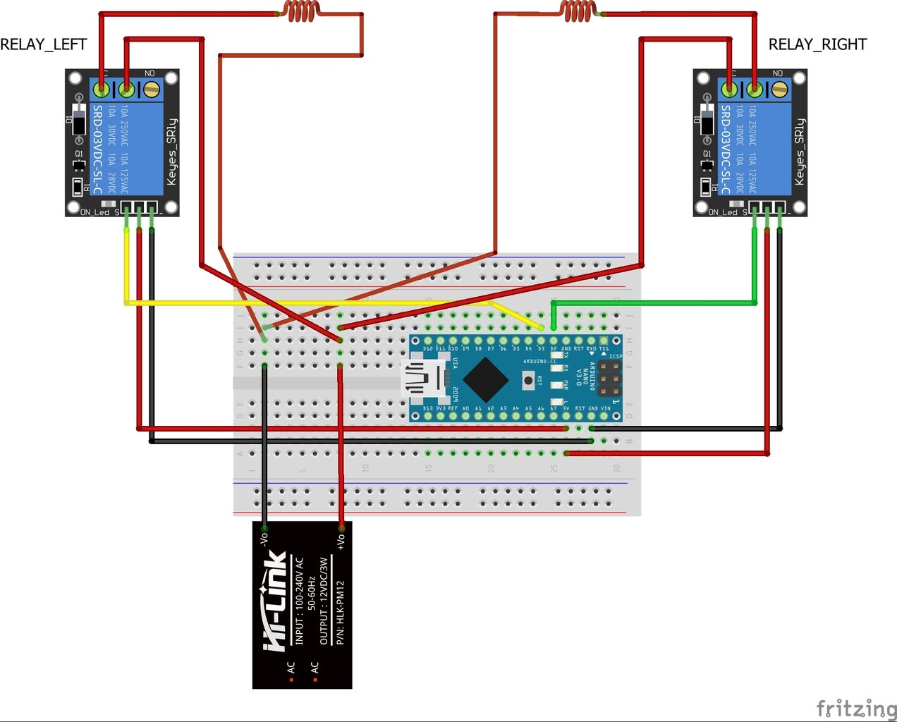
Two reles will control the magnetic field generation on each coil and everything controlled by the following ARDUINO sketch
#define RELE_RIGHT 2
#define RELE_LEFT 3

void setup() {
	pinMode(RELE_LEFT, OUTPUT);
	pinMode(RELE_RIGHT, OUTPUT);
}

void loop() {
	#define delaymovement 2000

	digitalWrite(RELE_LEFT, LOW);
	delay(100);
	digitalWrite(RELE_RIGHT, HIGH);
	delay(delaymovement);
	digitalWrite(RELE_RIGHT, LOW);
	delay(100);
	digitalWrite(RELE_LEFT, HIGH);
	delay(delaymovement);
}
You can see the final result in the video.
Attachments
Step 12: Final Project: Build an Electromagnetic Induction Based Led Lighting


Applying what the students learned they must to build and electromagnetic induction based led lighting.
The design of the project could be free or to build the design you can see in the pictures.
In this design you can see three electromagnetic coils with 1700 turns of wire that can induce the EMF needed to lights four 5 mm red and yellow leds. In this project one red and one yellow led has been mounted inside of six ping pong balls. Four leds or two ping pong balls are connected to one coil.
In the video you can see the final result moving at a frequency of 250 ms.

Grand Prize in the
Teacher Contest


