

Introduction: Emergency Lamp From a Cell Phone


Do you have an old cell phone lying in the junk drawer? And the charger?
Use it to build an automatic LED emergency lamp that will come on whenever there is a power outage. It will also serve as a portable flood light.
Step 1: The Circuit

+Vin and GND are wired to the phone's power connector.
+Batt and GND are wired to the phone's battery terminals.
J1 is the power input from the cell phone wall charger. When there is a voltage at J1, the base of T1 will be high, which keeps the emitter low. A low at the base of T2 keeps T2 turned off.
When there is no voltage at J1, T1 switches off. The base of T2 goes high (through the pull-up resistor R2) and T2 switches on. The collector of T2 supplies ground to the LEDs and they illuminate.
I put R7 in the circuit to bleed the input voltage after a power outage. This prevents a long delay before the LEDs light up. If the delay is excessive (more than a couple seconds), lower the resistor value.
During use, switch S2 is in the on position. If not, the LEDs will not light when there is a power outage.
Pressing the pushbutton test switch S1 will light the LEDs only when there is a voltage at J1 and switch S2 is on. This will show that the unit is active.
With the power cord disconnected, the unit can be used as a portable lamp. Switch S2 controls the light.
Adjust the value of the current limiting resistors (R3-6) to get a bright light without smoking the LEDs.
A major part of the circuit is not shown...the cell phone's on-board Li-ion battery charger. Use the phone's original connector to ensure that the charger works correctly.
Schematic created using Eagle 6.4.0.
Step 2: The Box


1. The 'Signal Combiner' will be the lamp enclosure (Goodwill, 2 bucks). A piece cut from the plastic file box will make a frosted window. A wall transformer supplies the power.
Q: Is that a Goodwill price tag I see on the file box? Does it say 99¢?
A: You betcha! That's where I do my best shopping. BTW, all blue tags were half price that day.
2. The enclosure is 3in x 4in x 1in high. Cut a large hole while leaving enough around the edges to mount the window.
3. The window is mounted with self-tapping screws. The two switches and the power LED have been installed.
4. For J1 I used an RCA audio jack. My first choice would be a 5.5mm power jack, but I didn't have one available.
Step 3: LEDs


1. The LEDs I used are clear super-bright style. The jumbo package is 10mm diameter.
The lens had such a tight focus that it made a bright dot on the plastic window. Sooo, I filed the tops flat to make the light more diffused.
2. Drill mounting holes in the board that are smaller than the screw diameter. Drill holes through the lid to match the holes in the board. Use standoffs to elevate the board.
Note from author: I haven't bought standoffs in so long I can't remember. Those are short lengths of vinyl tubing that slip over the screw. They work great for low stress applications, and they cost almost nothing.
3. Drive the screws through the board. Nuts may be needed if the holes strip out. Nice standoffs, eh? And cheap, too. Just like me.
Step 4: The Battery


1. We need to connect the battery to the lamp circuit.
Lightly tin the contact pads. Be careful not to blob solder where the pad makes contact with the board connector (the side facing the camera).
Tin the wire, place it on the pad, and touch the soldering iron to it until the solder melts. Quickly remove the iron.
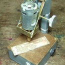
2. This was an old Kyocera flip-phone circa 2005. I disassembled the phone down to the bare board. The only part I'll be using is the on-board Li-ion battery charger.
The battery must sit on the board with the pads aligned with the board connector (those three contacts at the lower left).
The piece on the right is drilled for self tapping screws to mount the assembly.
Step 5: Phone Assembly


1. I tied the board, battery and mount together with nylon lacing tape. Ty-wraps will also work as long as there is solid electrical contact. Drill matching holes in the bottom of the box to mount the assembly.
(This mounting system is definitely not my best work. I must have been hung over that day.)
Looking back, I think I could have left the phone in the case. Maybe just remove the display and the antenna.
Hmmm. Would an incoming call make the LEDs light up?
2. Well, everything seems to fit OK.
Find a place to hang it, plug it in to charge the battery, and we're good to go.
Step 6: Final Thoughts

The main reason I'm posting this project is to show a novel way to recycle a dead cell phone. The builder can take it from there and design any sort of enclosure he chooses.
Personally, charging Li-ion batteries scares me. I've heard too many stories about laptops (and jumbo jets) overheating and catching fire. I trust the cell phone on-board charger to do the job with little chance of a mishap.
Thanks for looking
wotboa


