

Introduction: Ergonmic Down-View Monitor Adapter


A down-view monitor workstation is a method of placing a computer monitor below eye level for ergonomic reasons.
Commercial, pre-built down-view desks and adapters are available but expensive.
Here is one way that you can make a down-view monitor contraption that is adjustable and portable. And cheap.
Step 1: Main Idea

The main idea of a down-view workstation or adapter is to position the monitor below eye level. It's not a popular concept among the ergonomic experts (erogperts) since anything other than 90 degrees (for any position be it neck, arms, or legs) is anathema.
However, my funny friend Lax has been testing out the down-view theory and, for Lax' situation at least, it has seemed to help.
We'll keep this 'able posted with Lax' analysis and, in the mean time, you can build your own adapter.
Step 2: Architecture

It consists of four basic pieces:
- A top (which the monitor rests on)
- A bottom
- A lip (to keep the monitor from slipping down into your lap)
- A stabilizer (two triangle wedgies) (used to adjust the angle of the monitor)
Step 3: Architecture, Cont.

I have a hard time with spatial reasoning, so here is another set of views of the adapter, note the colors used to represent the main parts.
I tried to apply the same colors throughout the 'able to help keep the parts identifiable.
Step 4: Tools & Materials

Tools
- Electric drill
- Circular saw
- Jig saw or pointy or drywall saw
- Pencil
- Plywood for top and back (Plywood mostly comes in huge honking sheets but you can have the people at the hardware store cut it in half so it can fit in your car; there are also some sheets that are not as honking)
- Non-mortised hinges
- Golf Tees to use as removable pins
- 1x2 strips for lip and stabilizer
- 2x4 block for stabilizer triangle wedgies
- Wood glue
- 150, 220 grit sandpaper
Step 5: Cut Top and Bottom Sheets and a Lip

Based on the size of the monitor, use a circular or jig saw to cut a square top and matching bottom plywood sheet.
Then cut a 1/2 board to the same width as the top and bottom.
Since I have problems with spatial reasoning and visualization, I used PhotoSlop to emphasize/highlight which piece is which.
So the cinnamon color is the bottom, cyan is the top, and lemon is the lip (just as in the architectural cartoon)
Step 6: Hinges

I also have a problem with hinges.
Ahem.
(PS - anyone know how to get a screwdriver out of a door hinge?)
Step 7: Hinges, Cont.

I used these non-mortised hinges.
But who ever heard of Doors with out Jim Mortise? Anyway, these just seem easier to use.
Step 8: Apply Hinge to Bottom Sheet


The first part of the hinge isn't too difficult.
Close a hinge, place it atop the bottom (see what i mean about spatial reasoning?) cinnamon sheet's edge.
Mark the holes of the outer part of the hinges.
In the second figure, (profile), you can see (sort of) how the hinge is slightly indented and "wraps" down the side of the bottom cinnamon sheet.
Step 9: Apply Hinge to Bottom Sheet, Cont.

Drill holes where the marks were made, and attach the hinges to the bottom cinnamon sheet.
Repeat with the other hinge.
Step 10: Attach Lip to Hinge

Position the lip piece on top of the bottom sheet at the bottom edge.
Or
Position the yellow strip along the edge of the cinnamon sheet near the hinges.
Step 11: Lip to Hinge, Cont.

Flip the hinge up to meet the lip.
Step 12: Lip to Hinge, Cont.

Mark the holes of the hinge on the lip.
Step 13: Lip to Hinge, Cont.

%$#@!
Watch your mark.
Step 14: Lip to Hinge, Cont.

Drill where the holes are marked, and screw in a screw to hold the hinge to the lip.
Tip: if the screws are too short, use a piece of cardboard to hold the screw like a pair of tweezers while inserting screw.
Step 15: Bottom, Lip Hinged Result

You should have something like this, with the lip hinged to the cinnamon (back) sheet.
Step 16: Attach Top Sheet to Lip

Flip the lip up
Step 17: Attach Top Sheet to Lip, Cont.

Position/slip the top (cyan) under the lip
Step 18: Attach Top Sheet to Lip, Cont.

Mark on the top (cyan) sheet where the lip meets
Step 19: Attach Top Sheet to Lip, Cont.

Flip the lip back down and apply glue to the edge of the top (cyan) sheet up to the marker line
Step 20: Attach Top Sheet to Lip, Cont.

Flip the lip back over the top (cyan) sheet and clamp.
Why? I'm a klutz and have found that when dealing with awkward angles, it's sometimes easier to glue and clamp things together before trying to screw them together. Or just skip this step.
Step 21: Attach Top Sheet to Lip, Cont.

When the glue dries, you can see how the lip is now connected to the top (cyan) sheet.
Now use a drill and screw the lip into the top sheet.
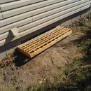
Step 22: Progress So Far


You should now have the basic stand: a bottom (cinnamon) sheet hinged to a lip (yellow) to which is attached the top (cyan) sheet.
Step 23: Important: Make a Handle


- Close the stand
- Sketch outline of a handle at the opposite-of-the-lip-side of the top sheet (see how hard this is to explain for even a simple idea?)
- Use a large drill bit and drill a hole at each of the corners of the handle outline. Go all the way through the top (cyan) to the bottom (cinnamon) sheets. Why? The hole will help guide the saw when cutting out the rest of the handle. Sort of.
- Use a jig saw or the kind of saw they cut drywall with (can't remember the name right now but it's small and skinny and can fit in tight places) and cut out the rest of the handle.
- Use some 150 and 220 grit sand paper to smooth the handle
Step 24: Optional: Botox for the Lip

This is an optional step. The lip (yellow) is meant to keep the monitor from sliding down the adapter and crashing into your lap or onto the floor. However, I couldn't remember how deep the monitor was so I wanted to be sure that the lip would be big enough to keep it from sliding off.
But, at the same time, I didn't want the lip to block any view of the monitor in case the monitor wasn't as deep as the lip.
So I wanted a way to make the lip bigger but yet have it be smaller if needed.
Step 25: Optional: Botox for the Lip, Cont.

This is the only photo I took of the optional lip on steroids because I wasn't sure it would work, but it did work.
In the photo, concentrate on the yellow strip (with the drill) -- that is the original-sized lip.
Above that strip, notice another yellow strip with what looks like a golf tee sticking out of it on the right side.
So this is basically just a wider strip with a long notch cut out of it and held in place with golf tees on each end.
I used golf tees so that they could hold the larger lip implant in place yet are easy to remove and allow the implant to be removed easily as well.
Step 26: Stabilizer

Start out with a 2x4 block (about 6 inches long or so) and bisect it corner to corner. (Make little triangles.)
NOTE: I'm not sure the triangles are all that important, you could just use two 2x4 blocks
Step 27: Stabilizer, Cont.

I don't show the details, but saw down another 1x2 to a few inches less than the width of the top/bottom pieces. This will act as a cross-piece for the stabilizer triangles.
Lay out the triangles and cross piece.
Why? The purpose of the cross piece is to allow the user to be able to move the triangles up and back easily (changing the viewing angle) without having to adjust both triangles at a time. I just found that during the prototyping stage it was a hassle to get one side up and then trying to get the other side up to the same height. But whatever, no big deal.
Step 28: Stabilizer, Cont.

Here, I made the hole large enough for a golf tee so that I could both:
- Twist the little triangles to the sides for a smaller angle and so that I could lie them flat when carrying the adapter (more on that in a bit)
- Be able to remove the triangles from the cross piece if I changed my mind and thought the cross piece it was dumb
Step 29: Stabilizer, Cont.

Note how the golf tee sticks out like a nub. That is used as an advantage in a few steps.
Step 30: Stabilizer, Cont. (Optional)


I'm the laziest person on the planet and so I though it would be very handy to keep the stabilizer piece with the main body of the unit when I have to move it.
So in this step you can line up the nubs on the back of the stabilizer, mark where the nubs hit the lipdrill a few holes in the lip, and, when carried with the handle, the stabilizer will sit recessed in the lip.
Step 31: Add Rubber Feet to Back Piece


To keep the whole thing from sliding off the desk top, cut up a mouse pad from a defunct dot-com (or some other medium that goes no where) and glue to the bottom of the bottom (cinnamon) sheet.
Step 32: Final Project Complete


First figure shows the adapter with the stabilizer set to its lowest level. (Of course you can move the stabilizer back further or use something smaller like a pair of dice to use as a stabilizer for a smaller angle.)
Second figure shows the adapter with a larger angle. Again, note how the triangular shape of the stabilizer triangles don't really do much; you could just use rectangles here.
Step 33: In Action

Here are a few 15-second clips of putting the thing together and breaking it down.

Participated in the
I Could Make That Contest


