

Introduction: Create External Interrupt in Arduino
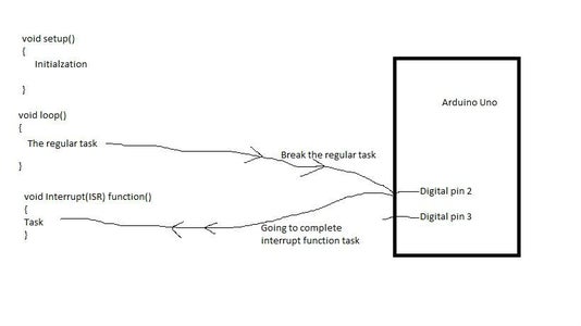


Adruino has several types of interrupts.Interrupt is a process by which arduino stops its regular task or stop its looping and go to interrupt function to complete its given interrupt function task.External interrupt created externally.There are only two external interrupt pin in arduino uno. They are Digital pin 2 and Digital pin 3.
After initialization of external interrupt if there is any change in signal in this pin. Then that will create external interrupt.
Step 1: External Interrupt Pins
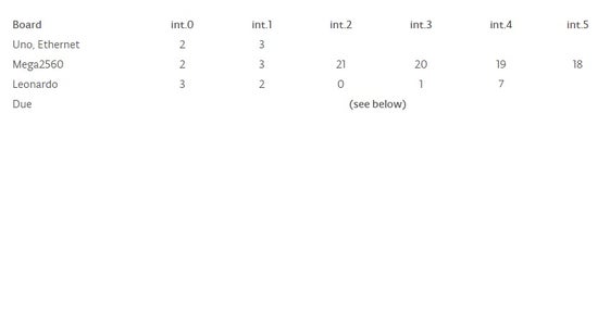
Arduino uno has two external interrupt pin Digital pin 2 and Digital pin 3.
Arduino Mega has 6 external interrupt pin Digital pin 2, Digital pin 3, Digital pin 21, Digital pin 20, Digital pin 19 and Digital pin 18.
Step 2: Arduino AttachInterrupt() Function
attachInterrupt() function is used for creating external interrupt.
Syntax
attachInterrupt(interrupt, ISR, mode)
attachInterrupt(pin, ISR, mode) (Arduino Due only)
Parameters
interrupt:the number of the interrupt (int)
pin:the pin number(Arduino Due only)
ISR:the ISR to call when the interrupt occurs; this function must take no parameters and return nothing. This function is sometimes referred to as aninterrupt service routine.mode:defines when the interrupt should be triggered. Four contstants are predefined as valid values:
(1) LOW: to trigger the interrupt whenever the pin is low,
(2) CHANGE: to trigger the interrupt whenever the pin changes value
(3) RISING: to trigger when the pin goes from low to high,
(4) FALLING: for when the pin goes from high to low.
The Due board allows also:
HIGH to trigger the interrupt whenever the pin is high. (Arduino Due only)
Returns:
none.
You can also see this from arduino page.Link:https://www.arduino.cc/en/Reference/AttachInterrup...
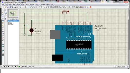
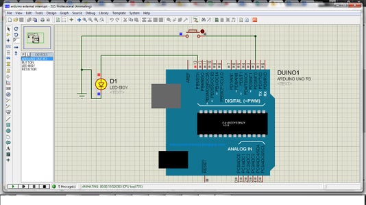
Step 3: Writing a External Interrupt Code (step-1)
Aim to do: We will initialized our aruino to sense the external interrupt in digital pin 2.Through this external interrupt we want to complete a task.The task is, toggle LED on pin 13.That is if the led in the 13 pin is on,then after getting the external interrupt 13 pin is off.
N.B:In the interrupt function delay() and millis() does not work.But,you can only use delayMicroseconds().
Lets do it.......
Step 4: Writing a External Interrupt Code( Void Setup()) (step-2)

In void setup() we have to initialized the digital 13 pin as output and interrupt function attatchInterrupt().
void setup()
{
pinMode(13, OUTPUT);
attachInterrupt(0, blink, FALLING);
}
Here, Pin 13 is declared as output.In attachInterrupt() function first parameter is "0".This is zero because we will use digital pin 2 as external interrupt.Here "blink" is an interrupt function.You can give any name if you want.There are four state in mode they are LOW,CHANGE,RISING,FALLING and an extra one for arduino due HIGH.We use FALLING.Arduino works in digital signal.In the digital signal has four state.They are showed in figure.We use FALLING ,it mean whenever in pin 2 sense a falling edge signal, it will go to interrupt function.And complete the task.
Step 5: Writing a External Interrupt Code( Void Loop()) (step-3)
Normally in this code We don't do any thing in the loop.But you can add any kind of task through the code.So in my case:
void loop()
{
//Add your task
}
Step 6: Writing a External Interrupt Code( Void Blink()) (step-4)
Now, we will write interrupt "blink" function.Since this is an interrupt function.So in this function we can not use delay() and millis() .But,we can only use delayMicroseconds().
void blink()
{
digitalWrite(13, !digitalRead(13)); // Toggle LED on pin 13
}
Step 7: Writing a External Interrupt Code( Final Code) (step-5)
void setup()
{
pinMode(13, OUTPUT);
attachInterrupt(0, blink, FALLING);
}
void loop()
{
//Add your task
}
void blink()
{
digitalWrite(13, !digitalRead(13)); // Toggle LED on pin 13
}


