

Introduction: F1 Exhaust Lamp


So, this is a first for me, I've been meaning to write an instructable for a while but have never actually done it so please go easy on me:)
Formula 1 Exhaust Lamp
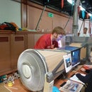
This lamp is made using used Formula 1 race car parts. I have always loved the organic twisting set of tubes that multi-cylinder exhaust manifolds use, so when I found an exhaust on eBay I knew I could make it into something. While designing the lamp I decided to add an F1 wheel as a base to add to the overall effect; the result is above.
The parts are getting more common now so I'm writing this instructable so that you too can make a nice feature lamp with real racing pedigree.
Step 1: Selecting the Key Components


The Exhaust
Clearly the first thing you need to do is find an exhaust. These can be very expensive if you are precious about the condition or want a matching pair. Look at F1 parts sites like F1-247 for these but be warned they can cost well over £1,000 each. I got mine cheaper due to a small dent in one of the tubes (this will face the wall anyway!) and I picked mine up from eBay. They can often be seen starting from £100-200.
Mine is from a Williams V10 (thought to be FW27 car but no idea if that is right). Different cars' exhausts have different looks and the V10 era clearly had an extra pipe which I quite like, so do think about the look you are going for when selecting your pipes.
Also I have learned from my mistakes that despite the exotic Inconel metal used to make this exhaust being inert enough to not burn away when red hot stuck to the outlet of a revving F1 engine, it appears to oxidise in the presence of the acidity found in finger grease. Be careful where you touch it or use gloves!
The Base
I decided to go for a floor standing design so needed a heavy base to keep the lamp stable. There are a few options for the structural part of the base. Normal lamps often use granite bases if they need the stability and gym weights could be used as ballast if necessary, but I chose to buy a bar stool to dismantle for the purpose. These can be picked up for £5-10 quite easily and have the perfect combination of a heavy base and a sturdy stem that will take more weight and off centre load than you will ever need. The stool I used was adjustable height with a gas strut. To dismantle it I only needed to remove one circlip from the base, allowing the stool and gas strut to be slid up and removed, leaving the base and stem.
While the chrome base matched the aesthetic well, I couldn't resist buying an F1 wheel to add to the overall effect. I managed to get a 2010 Red Bull Racing wheel that a certain Mr Webber was driving around on for under £100, again from eBay. The stem from the bar stool is long enough to poke through the wheel so I didn't have to structurally attach the shaft to the wheel. For those who want to know the dimensions to see it will work for them, the ID of the wheel nut hole is 56.5mm on my wheel. The wheel width is 335mm and the diameter is 355mm (only ~13"!... Bizarrely the same as my classic Mini).
The Stem
For the stem I used a 1.2m long section of mirror polished 2.5" stainless exhaust. This is surprisingly cheap but not that easy to find polished. Suppliers I found were MIJ exhaust and stainlessonline who both trade on eBay.
I selected the diameter to match as close as possible the 66mm OD of the F1 exhaust. The length was selected to make the lamp the height I wanted. Because the tube was wider than ID on the wheel I chose the length based on it starting on top of the wheel; if you don't add a wheel to your base, make the tube a little longer to make up for it.
Step 2: Structural Attachment


So having selected all the big bits we need to attach them together...
There a two big joints that need to be made, base to shaft and shaft to exhaust:
Base To Shaft
I was keen to avoid any modifications to the F1 parts so I designed everything to be a sliding push fit.
This joint needs to transfer vertical weight of the rest of the lamp. I designed and 3D printed a spacer that slides over the stem from the bar stool base and presses into the wheel, centralising it on the base. The angled section on this spacer allows it to transfer load down onto the wheel, and the upper surface of the spacer has a deep groove into which the stainless tube can be pressed, thereby transferring the weight from the shaft to the wheel, which in turn sits on the base.
The base to shaft joint also needs to take moment load to stop the stem leaning relative to the base. To give good moment support it is always best to attach parts in at least two places that are separated to give some leaverage. In order to achieve this I also designed and 3D printed a spacer cap that sits at the top of the base stem and slides inside the tube to locate the shaft and prevent it from leaning. I tested the fit of this before wiring anything and was pleased with how well this simple approach worked. Don't forget we need a hole in the spacer for the wiring to get up from the base.
Since my work got an Up Plus v2 I tend to 3D print my way to a solution whenever I need to solve a problem, but I realise many people won't have access to a 3D printer. Fear not! There are at least 2 solutions:
- Online suppliers such as shapeways and i.materialise offer relatively low cost SLS parts.
- Alternatively you could go oldskool and turn the spacers in a lathe or at a push you could even rout them out of wood (using a hole saw for the groove). The same will go for the other 3D printed part below.
Shaft To Exhaust
This joint is slightly trickier. While the moment load is lower, the off centre weight of the exhaust still puts a constant bending moment on this joint. I selected the shaft tube to be the same diameter as the exhaust so we can't use the same trick of having two load transfer points between concentric tubes. Instead we need to make a butt joint connector that slides sufficiently far inside each part to take the bending moments without excessive stress. I based the deign on the maximum build area of the Up 3D printer I was using so the connector goes about 50mm up iside the exhaust and down into the shaft tube. To spread the load better I also designed in a groove for the tubes to slide into to locally support the tubes where they naturally pull away from the connector insert inside them. I used a tighter fit here too to stop the lamp from being crooked, so when testing the fit I didn't push it all the way (as you can see in the photo). A further complication comes from the limitations of low cost 3D printing; using ABS means that if I were to print this part sideways for maximum strength it would warp, so it needs to be chunky to stop the weak joins between layers from separating. We do still need a hole up the middle for wiring here too.
Step 3: What Good Is a Lamp With No Lights


OK so now the lamp is looking pretty awesome, but something is missing...
Once you are happy with the fit it is time to disassemble the lamp again ready for lights and wiring to be fitted.
I selected G4 bulb holders for the lamp for a number of reasons:
- They fit nicely and the bulbs are an appropriate size
- They are 12V which is much easier to make safe without having to screw earth wires to my precious F1 parts
- There are available LEDs for this size for lower energy usage
- The 12V means I can retrofit some arduino powered awesomeness for control and dimming, etc.
Unfortunately the LED bulbs I ordered have taken forever to arrive and I cannot buy them in my local hardware store, so in this instructable I used halogen bulbs. This has made my 3D printed bulb attachment parts pretty useless as they would get way too hot, and I have had to uprate the wiring and power supply for the higher current. I will retrofit the LEDs when they arrive and will try to post an update.
For now I wanted my light so I pressed ahead with the halogens. The bulb holders I bought are ceramic and seem to have a heat reflector so I figured they should be fine with the heat, but I needed to attach them to the exhaust, without modification and in a heat proof manner. After rooting around in my garage I managed to find some plain steel wire, so decided to use this. It doesn't look pretty close to, but is hardly visible from afar and not at all when the light are on. It is after all only a temporary measure until the LEDs arrive.
My method of attachment is the same as for my 3D printed option. Where the exhaust manifold comes to meet the head it splits into two almost separate paths feeding from each of the valves. The result is the circular section tube narrows into a figure-8 shape while getting taller into the height of the 8. By forming two wings that sit in the top and bottom of the 8 the holder bracket can prevent itself from falling further into the exhaust. Forming a further two wings on the sides that press forwards against the narrowing in the middle of the 8 prevents the assembly from moving outward or falling out of the exhaust. Together this is enough to secure the holder in position behind the opening in each tube. Whichever way they are made the wings need to be flexible enough to enable the insertion of them.
For each bulb holder mount I used about 500mm of wire. I strongly recommend folding the cut ends of the wire over using pliers to prevent scratches from the sharp ends, especially as it will ping into your eye as soon as look at you.
My bulb holders had 2 screw holes so I tied the wire on here, then wrapped it round the holder to control the angle better, then tied it off again. The remainder of the wire was then used to form the 4 wings required (see images). This is not a precise art as the wire has plenty of spring and can be adjusted later for fine placement of the bulbs.
Step 4: Wiring It All Up


Having checked fit, the next step is to wire the holder into the supply. The flying leads were too short to reach to where the pipes joined together so I crimped them onto some 2-core extension cable (pictured).
It is then the fun game of trying to feed the wires from the 5 bulb holders down the five twisting pipes. I used a mixture of pushing, shaking, gravity and patience combined with a small amount of hooking with some of the spare steel wire. While not a quick job you will get there soon enough! Once you have 5 pairs of wires coming out of the exhaust it is time to join them together. Once again I used crimps, although in hindsight with 5 into 1 it may have been easier to use terminal blocks or solder. The other side of the crimp is connected to some 1.5mm2 cable to carry the high current from the halogens. This cable needs to be long enough to reach the power supply.
I heatshrinked the joints individually and then together to add some strain relief to the crimp connection. The cable then needs feeding through the butt-joint connector and this should be pressed firmly onto the exhaust. Then the cable is fed through the shaft tube and again this is pushed firmly into the butt joint.
The base on my bar stool had a rubber strip around the edge that it stands on. Carefully gouging this with a knife gives a groove for the cable to exit through. Then reassemble the base assembly ready to fit to the rest of the lamp.
Next the cable needs to be passed through the base stem. Remember to do this after fitting the wheel and ALL the spacers. This was particularly tricky as the end of the base stem has a plate welded that the circlip sat against and this has only a small hole for feeding the cable through. Here is where hooking the cable with your spare steel wire is order of the day. There was a significant feeling of relief when I finally got the cable through the base.
The shaft can now be slid over the spacers and pressed firmly into the groove to finish the assembly.
Step 5: Testing, Finished Lamp and Next Steps


A couple of quick tests
Before fitting the bulbs I checked for any shorts across the supply. There weren't any (phew!) so I fittted the bulbs. A small amount of tweaking of the wire holder supports was needed to get all the bulbs central, level and slightly sub flush with the ends of the tubes. I then connected the set up to my lab pack and gradually turned up the voltage with the current limit on. Everything behaved as expected so I wired it into my 12V 6A power supply (make sure yours has short circuit protection on or else add a fuse).
One finished lamp!
Here are a few more views of the lamp in all its tuby glory:)
Next steps
My first step will be to fit LED lighting and then downsize the power supply.
I also want to fit a gear concentrically around the butt-joint that can be rotated to act as a dimmer switch
After that I want to make the lamp smart. Perhaps range finders in the tubes to control with gestures, individual lamp control, remote control, automatic timers, motion sensing... You know the sort of thing!
I hope you all enjoyed this my first instructable.
If you did please vote for me in the wheel contest. Alas the lamp and lighting contest is US only:(
Also have a look at my website for other projects I have been involved in:

Participated in the
Wheels Contest


