

Introduction: FAIL! A/C-Duino: Arduino Upgraded Air Conditioner


This project was a failure and I gave up after the A/C unit destroyed itself. I began this project about 4 or 5 years ago when there was no such thing as a smart-window A/C unit. Now things like this make this project kinda silly, but at the time it was a fun project.
Since there is a new contest for Epic Fails, I figured I would revive this Instructable and submit it for the contest. The following italicized text is what I was writing as I worked through this process while I was still hoping for success.
I have very small windows in the upstairs of my little, old house, and I am limited to the smallest air conditioners available to fit in the windows. I hate that these small air conditioners don't come with the features that the larger units come with. I'm also surprised that no company has attempted to improve the efficiency of their window air conditioners with a real 7 day programmable thermostat like central HVAC units have. I decided to improve my air conditioner with my Arduino Uno and a custom shield that would replace the controller card in the A/C unit.
Step 1: Analyze Controller Board


I have looked at some repair sites and it seems that most air conditioners have the same basic design inside. There are 2 boards: a "Display board" and a "Main board". The display boards usually have two 7 segment displays, LEDs, tactile buttons, and a PIC of some sort.
I prefer to call the "Display board" the controller board because it has a PIC microcontroller and has all of the controls for changing the settings, not just displaying the status. The "Main board" seems more like a relay board to me, and while it does all the heavy lifting, the brains are all on the controller board so I will call this the relay board.
I read the model numbers off every part I could see on the controller board and typed them into a search engine. You would be surprised what you can find out about the components on a circuit board. The microcontroller is a 20 pin, 8 bit, PDIP, HMS87C1202A Microcontroller, made by Hynix Semiconductor. The other 2 chips are a SN74HC164 Shift Register and a 24LC01B EEPROM.
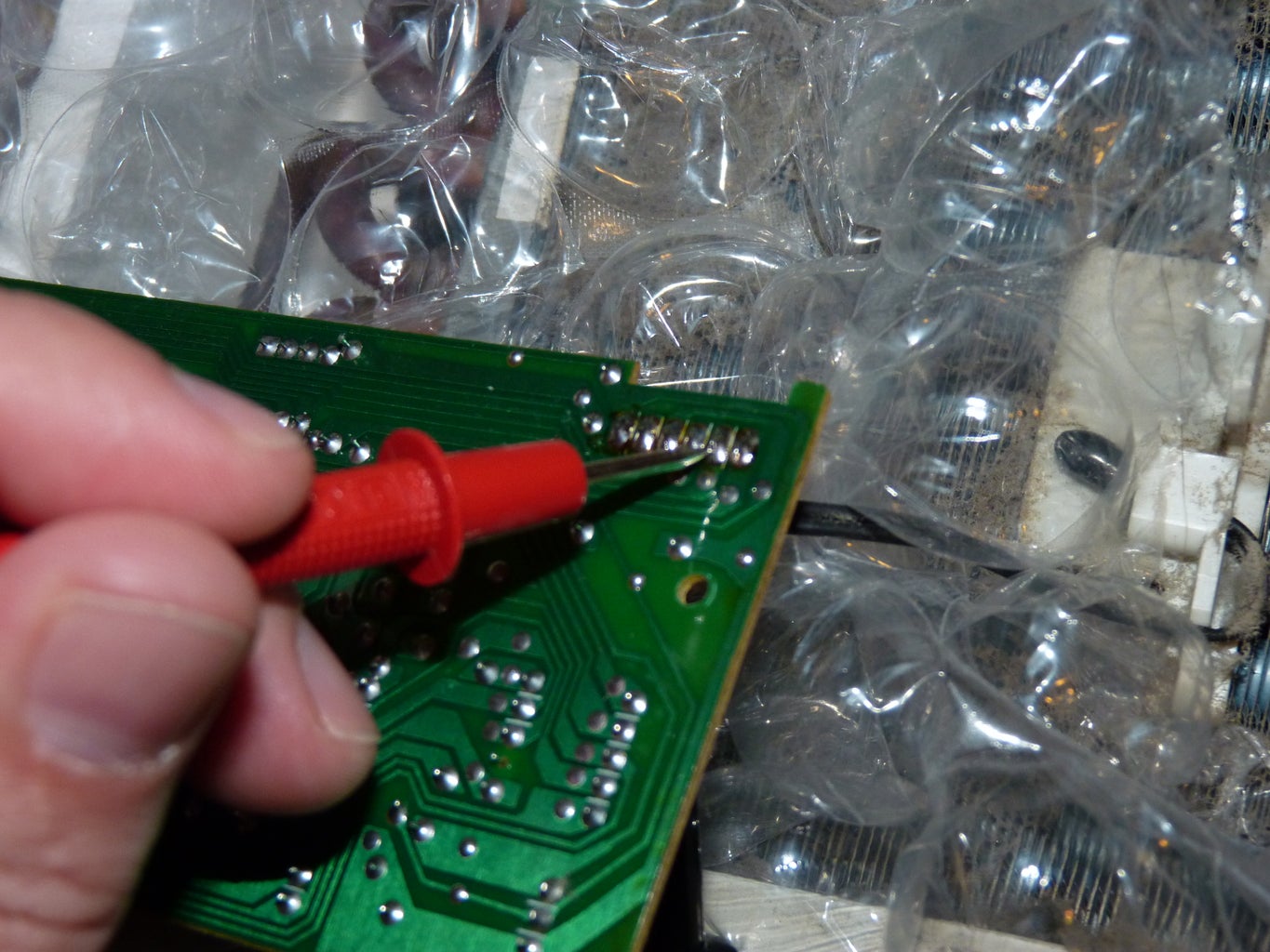
I used my multimeter and some multimeter ends I made to analyze the existing controller board. The controller board had VCC and GND silkscreened onto the single-sided circuit board. I clipped the black lead to a jumper I traced back to ground and used the bare point of the red lead to test voltages going out to the relay card for various states. I cycled the air conditioner through high and low fan modes, and with the compressor off and on. I was able to isolate the separate wires for the fan speeds, compressor control and the beeper and I measured the voltage on each wire to be +5v. These voltages switch on relays on the relay board further inside the A/C unit.
Step 2: Customize Controller Board

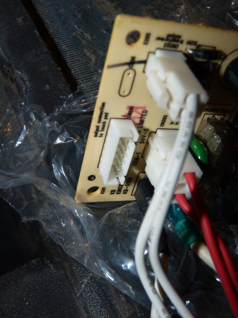


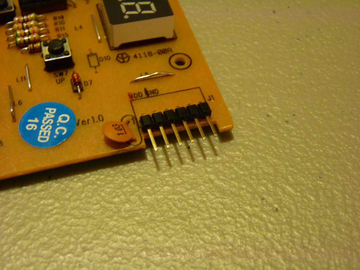


I wanted to make sure I could always put the original controller back in the air conditioner, so I needed to be careful with the wire harness that went between the controller and relay boards. On one end it was a 6 pin plug that I couldn't easily find for my replacement board, so I decided to remove the soldered end and add header pins so I can use the harness for both the new and original controller boards. (I have since found similar connectors on the JST website. This one was similar to the SJN connector)
I happened to have a plug that would connect to 8 header pins. I soldered and heat shrink insulated the wires to make a new wire harness that can be disconnected from the relay board and used with either controller card.
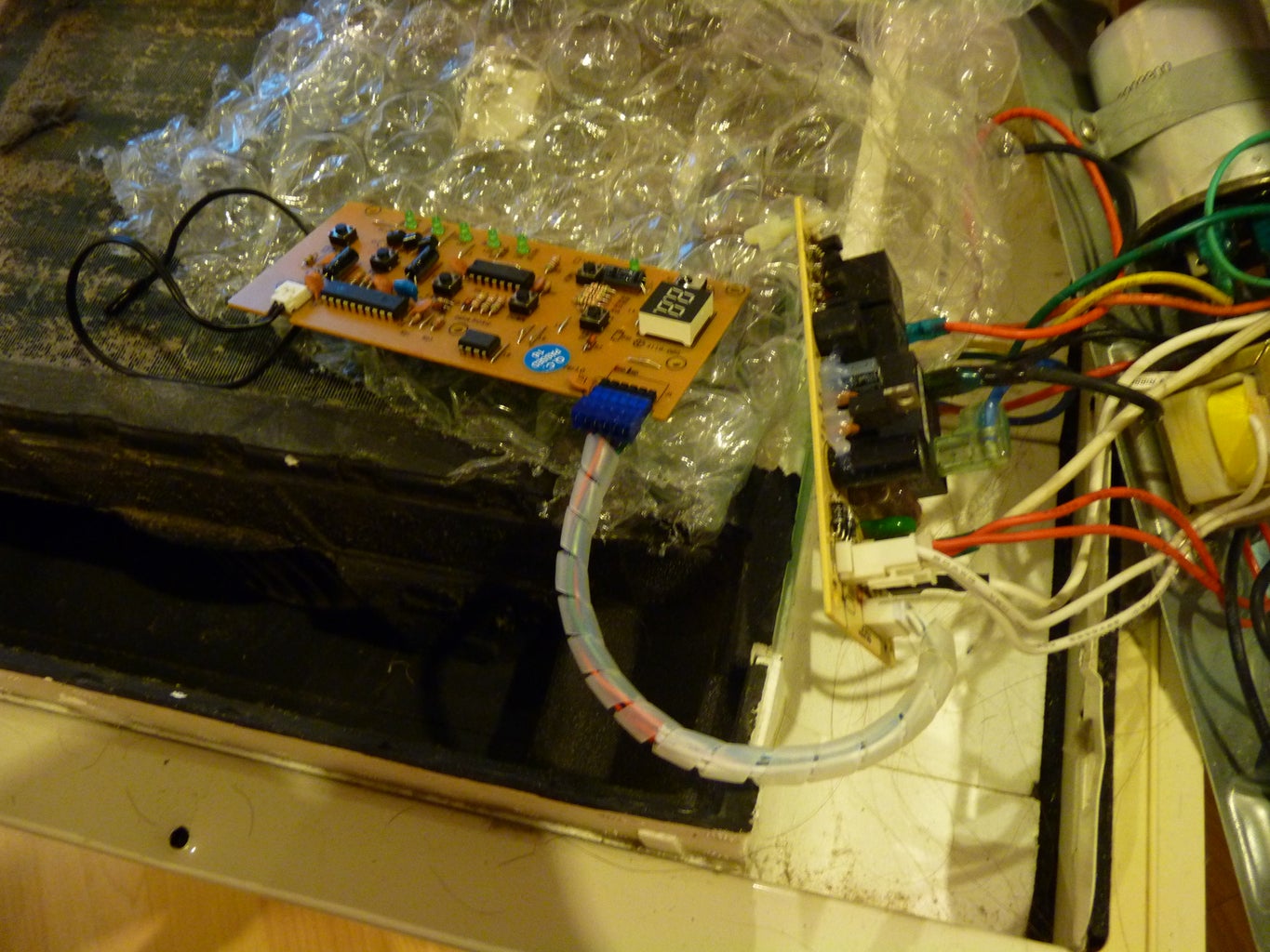
Update: I realized that the front bezel of the air conditioner wouldn't fit over the pin headers and the wires, so I took out the original pin headers and replaced them with some right-angle headers. While I was at it, I cut off the end of the wire and replaced the connector with one that lays flatter and only had 6 terminals. The new connector is an IDC (insulation displacement connector) that I grabbed from an old printer but I found a bunch of similar connectors here. I used some spiral cable wrap to keep the 6 loose wires neat and tidy. The longer wires make it easier to work with the board while it is not installed in the machine.
Step 3: Thermistors


The air conditioner has one thermistor in front of the coils that will sense the room's air temperature before it goes over the cold coils. This is good for telling the microcontroller if the room is warmer than you want it to be, but not what the outside air temperature is. I wanted to know if the temperature outside was below the indoor temperature, that way I could just turn the fan on high instead of turning on the compressor.
I found some good epoxy coated thermistors on Adafruit that are exactly the same as the one I already have. The epoxy coating makes them waterproof so they should be perfect for mounting on the outside of the A/C unit. The wires come without a connector, so I used another of my IDC connectors to make the connection to header pins like the original thermistor.
Thermistors are resistors where the resistance varies with the temperature. To make sure this one worked as I expected, I plugged some header pins into the plug and used my multimeter to read the resistance as I held the probe in my hand and tried to raise its temperature.
Step 4: Circuit Design (first Attempt)


I'm including this step because I think it is important to show that not everything works the first time. Failures are an important part of the process.
I started out using part of my Plexiglas Arduino board to create a circuit that would control the relays just as the original board had.
My first problem was that I only tested one transistor on one pin to see if I could switch one of the A/C functions on using an Arduino I/O pin. Unfortunately, I took that as success and made a shield on a piece of single sided perf board. I don't recommend the single sided perf boards for Arduino projects, mostly because things need to be soldered to both sides of the board because they are meant to stack. Because I didn't test multiple transistors on the breadboard before I put everything together, everything came on at once. I suggest fully testing the entire circuit before you do anything permanent.
My second problem was that I was trying to use the standard NPN / Relay circuit that you find everywhere with relays that were on another board and part of a separate circuit.
The first attempt failed because I got a simple NPN resistor working for switching one component, and I assumed that I could replicate that for the other 2 components without mocking everything up. I went ahead and designed the completed circuit on-the-fly on perf board. When I finally tested the completed circuit, it did not work. Somehow, the components were all turning on together, and I had to start all over.
Step 5: Circuit Design (second Attempt)


After my first attempt didn't work out, I decided I had 2 possible solutions. Either I could make a replacement for the this specific Air Conditioner, or make something more universal that I could use on other A/C units. Initially, I intended just to upgrade this unit, but then I thought about how useful this would be if it were more universal.
I eventually ran out of room and had to separate the two projects. Now I have 2 project boards and plenty of room to work.
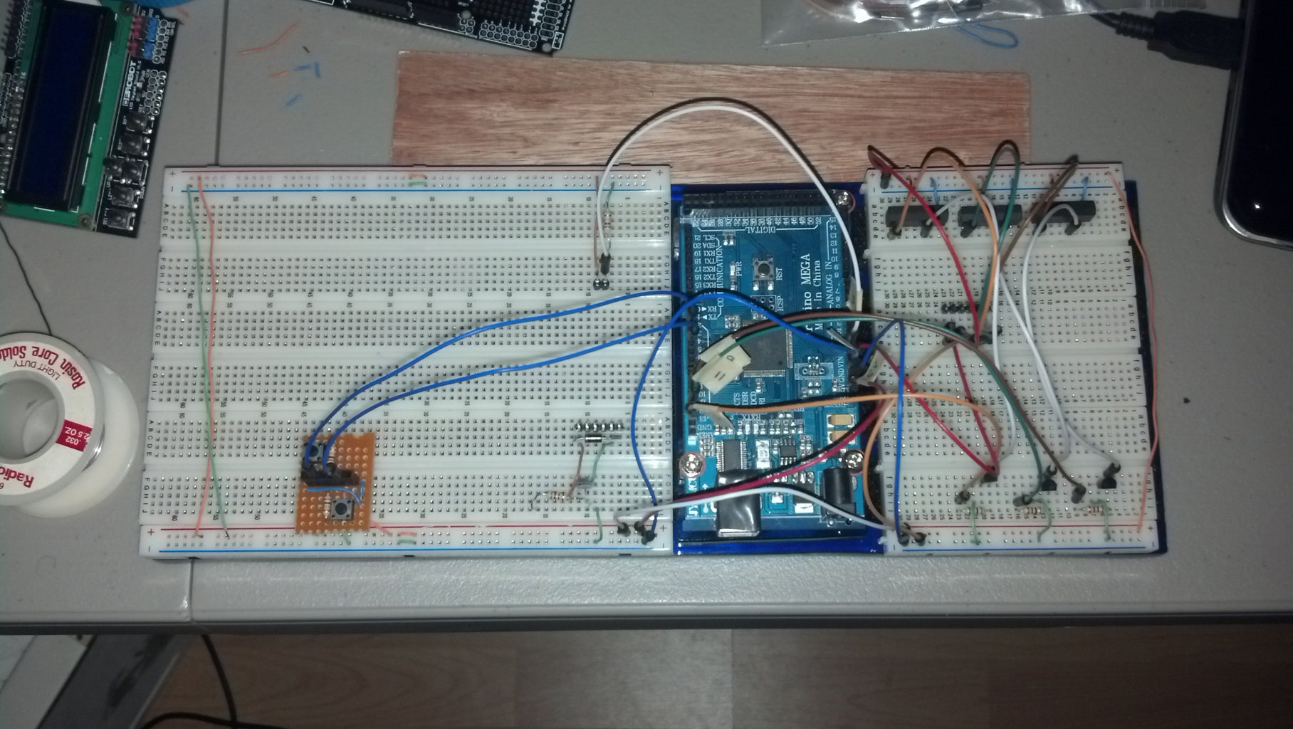
I connected the thermistor up to the breadboard and analyzed the output. Using the serial monitor on the Arduino IDE, I was able to see the temperature change as I held the thermistor in my hand. I used a laser temperature gauge to verify the temperature of my readings and everything was right on.
On the OEM controller, the microcontroller I/O pins were wired directly to the relay wires. I'm sure I could get away with this, but most relay tutorials explain that this is a bad practice and will shorten the life of the microcontroller. Originally, I was just going to use NPN transistors, but it was hard to find a solution that worked the way I wanted. I am not completely sure of the layout on the relay board, and even if I was, I want to make this design universal so I can use it on other models of air conditioner. I decided to use NPN transistors and some nice reed relays I found on Jameco. This type of relay includes a small coil suppressing diode, so I should be able to get away without an external flywheel diode. This is a pretty good tutorial for transistors and relays.
http://playground.arduino.cc/uploads/Learning/relays.pdf
Step 6: Custom Arduino Shields


I wanted a way to store settings, an interface to change them, and a display to show status and settings on a screen. At first I thought I could do this with an LCD shield I had, but unfortunately the pins it uses were conflicting with my SD card shield and my Ethernet shield. So, it was back to the drawing board...
Relay Shield
I have a couple protoshields laying around, but I needed something that would stick out past the end of the LCD shield and allow me to add some additional features, so I bought this longer protoshield for a Mega board. Unfortunately, it was $15 and I only used some of the headers and one of the buttons that came with it. It would have been cheaper to buy this bare proto board and a set of R3 stackable headers for the price of the full kit.
Display Shield
I bought a serial LCD screen (not a shield so I can change the pins to whatever I need them to be) and a Real Time Clock breakout board kit. I combined the LCD screen, the RTC module and a few headers for the thermistors into a Time & Temp Display Shield.
Step 7: Relay Shield - FAIL!

I never got around to writing this part up because just when I had some success, I had a catastrophic failure at the same time.
I had the circuit working, 3 NPN transistors with separate reed relays controlling the 3 main functions of the A/C unit. I had the Arduino cycling through the different functions and I was pretty happy with the result. I took a video and a few pictures and I was about to draw up a plan for the relay shield I would build. Suddenly there was a huge, loud POP and a few sparks shot out of the A/C unit. I quickly pulled the power and shut everything off, but the damage was done. The A/C unit made a loud hissing noise for a half hour and then stopped. I tried once to turn it on again but all it did was make a very loud buzzing noise.
My theory is that I ran the compressor through too many cycles without letting the refrigerant decompress. The pressure burst one of the lines, shorted something out internally and all of the refrigerant leaked out. It was loud and impressive and I was actually somewhat impressed with the result.
Step 8: FAILURE!

I worked on this project off and on for about a year, and I learned something very interesting when it failed. I can be completely satisfied with different outcomes of a project other than success.
When I begin a project, I always have to check to see if this is something I can actually complete. I don't want to dedicate time to something that I am going to abandon in the middle (I've done that too many times). So now I have a slow pre-planning process that weeds out the dumb ideas that are either too ambitious or just won't work.
This project was probably a bit ambitious, but I continued because I kept thinking it would work. I would put it away, pick it back up, tinker a little and I kept thinking it would be really cool if it worked. I wasn't going to be satisfied, and I couldn't stop tinkering with it unless I finished it.
When the AC unit broke, it was a relief in a way because the catastrophic failure was another way out of this project. I had a little success, but ran into other issues and ultimately the decision to keep going was taken out of my hands. The unit made a big POP and hissed and never turned on again. I took it down to the recycling center and I closed the book on this project.
Until now, this Instructable has hung out in my drafts folder with nothing I could do with it. I kept it around as a scrapbook to show people because I didn't think I could publish it. Thanks for making the Epic Fails contest! I think there is a place for this type of thing on Instructables.

Participated in the
Epilog Contest VII

Participated in the
Spectacular Failures Contest


