

Introduction: Fancy Blinking LEDs Using Arduino


This is fancy light generator which is built using Arduino . This project uses four LEDs and controlled using a microswitch(button switch) which trigger them to glow LEDs in different sequence and patterns....
Uno is one of the series of USB Arduino boards. The Arduino Uno is a microcontroller board based on the ATmega328. It has 14 digital input/output pins (of which six can be used as PWM outputs), six analogue inputs, a 16MHz crystal oscillator, a USB connection, a power jack, an ICSP (in-circuit serial programming) header and a reset button. It contains everything needed to support the microcontroller; simply connect it to a computer through a USB cable or power it with a 9V DC adaptor (or 9V battery) to get started.
Sequence....
On--All off
First--All on
Second--Flashing
Third--waving
Step 1: Components Required

*Arduino Uno
*4 LEDs (Any colour)
*Micro switch(button switch)
*wires
*Power supply(for arduino)
*bread board (if needed)
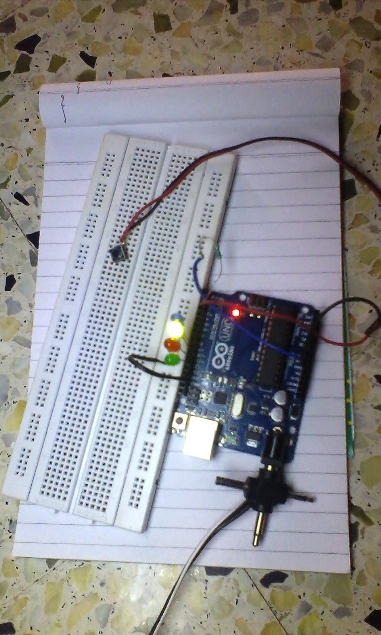
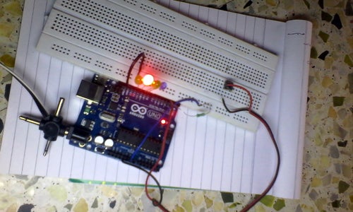
Step 2: Rig Up the Ckt

Here we use pin no 13,12,11,10 and 9 .
Resistors of 220ohm can be used to limit the current through LEDs...
resistor is very much needed between the ground and pin no 2....(10k is enough).
Step 3: Coding
// Fancy Lights Controller //
//By AP//
int switchPin = 2; // mode switch is connected to pin 2
int led1Pin = 12;
int led2Pin = 11;
int led3Pin = 10;
int led4Pin = 9;
int val; // variable for reading the pin status
int val2; // variable for reading the delayed status
int buttonState; // variable to hold the mode switch state
int lightMode = 0;
void setup() {
pinMode(switchPin, INPUT); // Set the mode switch pin as input
pinMode(led1Pin, OUTPUT);
pinMode(led2Pin, OUTPUT);
pinMode(led3Pin, OUTPUT);
pinMode(led4Pin, OUTPUT);
Serial.begin(9600); // Set up serial communication at 9600bps
buttonState = digitalRead(switchPin); // read the initial state
}
void loop(){
val = digitalRead(switchPin); // read input value and store it in val
delay(10);
val2 = digitalRead(switchPin); // Key Bounce Prevention
if (val == val2) {
if (val != buttonState) {
if (val == HIGH) { // check if the mode button is pressed
if (lightMode == 0) {
lightMode = 1; // turn LEDs on
}
else {
if (lightMode == 1) { // if LEDs on
lightMode = 2; // make it flash
}
else {
if (lightMode == 2) { // if LEDs flashing
lightMode = 3; // make it wave
}
else {
if (lightMode == 3) { // if LEDs waving,
lightMode = 0; // turn LEDs off
}
}
}
}
}
}
buttonState = val; // save the new state in our variable
}
// Now do whatever the lightMode indicates
if (lightMode == 0) { // LEDs-off
digitalWrite(led1Pin, LOW);
digitalWrite(led2Pin, LOW);
digitalWrite(led3Pin, LOW);
digitalWrite(led4Pin, LOW);
}
if (lightMode == 1) { // LEDs-on
digitalWrite(led1Pin, HIGH);
digitalWrite(led2Pin, HIGH);
digitalWrite(led3Pin, HIGH);
digitalWrite(led4Pin, HIGH);
}
if (lightMode == 2) { // LEDS-flashing
digitalWrite(led1Pin, HIGH);
digitalWrite(led2Pin, HIGH);
digitalWrite(led3Pin, HIGH);
digitalWrite(led4Pin, HIGH);
delay(100);
digitalWrite(led1Pin, LOW);
digitalWrite(led2Pin, LOW);
digitalWrite(led3Pin, LOW);
digitalWrite(led4Pin, LOW);
delay(100);
}
if (lightMode == 3) { // LEDs-waving
digitalWrite(led4Pin, LOW);
digitalWrite(led1Pin, HIGH);
delay(100);
digitalWrite(led1Pin, LOW);
digitalWrite(led2Pin, HIGH);
delay(100);
digitalWrite(led2Pin, LOW);
digitalWrite(led3Pin, HIGH);
delay(100);
digitalWrite(led3Pin, LOW);
digitalWrite(led4Pin, HIGH);
delay(100);
digitalWrite(led4Pin, LOW);
}
}
Step 4: Uploading and Executing


Now, click ‘File’ in ‘File’ menu and select ‘New.’ Here you can type or copy and paste the code inside the code window. Click ‘Verify/Compile’ button to check that the code is correct. If everything is fine, upload the code to your Arduino by clicking ‘Upload’ button. Presuming everything has been set up correctly, you will now see the RX and TX LEDs on the UNO board flash (switch on and switch off) very quickly whiledata is being uploaded to the MCU in the board. After the data is uploaded to the board successfully, you will get a “Done Uploading” message in the IDE and the RX/TX LEDs will stop flashing. The Arduino will now reset itself and immediately start running the sketch that you have just uploaded.
Step 5: Variable Adaptor

If everything is okay, remove Arduino from the computer and use it as a standalone unit. You can run the board from a 9V alkaline battery or a 7V-12 DC power supply using a standard 2.1mm male DC Jack plug (+ve in and -ve out)

Participated in the
Make It Glow! Contest

Participated in the
Arduino All The Things! Contest


