

Introduction: Feed Your Fish Flakes From Anywhere!


Feed your fish from anywhere in the world. Compatible with flakes! There are many fish feeders on the internet but not many that feed fish flakes. The main diet of my goldfish. I enjoy feeding my fish and when I travel I want to have that same enjoyment. This is also great if you forget to feed your fish. No more turning around on the way to work! The application also features a display showing the time of the last feeding. This will help you not over or underfeed your fish and for less thank $20 it's cheaper than many commercial solutions.
My first project with Arduino was an automatic fish feeder. With my lack of knowledge regarding both Arduino and 3D printing that project was not great. The goal of this project was to build a better version. I liked watching my growth, seeing how much better this version is. This feeder is based around the NodeMCU and the Blynk application.
Update: In humid climates such as tropical or coastal, the food tends to soak in moisture and become clumped and pretty gross. For people living in these climates, I'd recommend a design that keeps the food sealed when not in use.
Step 1: Parts and Tools


Parts
$8
$1.70
$4
21¢
$2
Smartphone - You'll need to download the Blynk app. Available on iPhone and Android.
Hot Glue - To attach servo in place and attach servo horn to shaker piece.
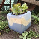
Fish Flakes Container - I designed the fish feeder to fit this bottle. You can also 3d print a bottle to fit. I bought mine in store at PetSmart.
Tools
Sandpaper - I used 100 grit. This may be needed to fit the servo in its slot.
Programs and Libraries
Step 2: 3D Printing


I designed the fish feeder on Tinkercad. I'm learning Fusion360 but am currently more confident with Tinkercad. The feeder prints in two pieces with an optional bottle to go along with it. The larger piece houses the bottle, servo, and NodeMCU. The second piece attaches to the servo horn. The food is shaken off of this piece into the water. Both pieces can be printed without supports. I used a 25% infill. The bottle is recommended but the fish food bottle from the parts page can be used instead. The larger piece took me about five hours to print and the servo attachment took about an hour and a half. You can find the files here: Printer files on Thingiverse
I'm currently printing on a MOD-t. Its cheap price and easy to use software made it a great first printer for me. However, I'd love a new printer as I'm growing as a CAD designer and inventor.
Step 3: Schematic


The NodeMCU is a microcontroller similar to Arduino. The difference is that it has a built in esp chip. This means without any external components it can connect to wifi.
The only connections made are between the servo and the NodeMCU. Connect Gnd to Gnd. The 5v of the servo attached to Vin of the NodeMCU. The signal wire of the servo then attaches to D1 of the NodeMCU. The NodeMCU has different pinout than your typical Arduino. D1 of the NodeMCU corresponds to pin D5 of the Arduino. Check out the pinout as well. In the code where we define our pin we have two choices. Either call the pin as "D1" or call it "5". Both options work.
Step 4: Making the App - Blynk


Blynk is an IOS and Android application that allows connection to microcontrollers through wifi, bluetooth, ethernet, etc. In this project we connect to the application over wifi. Blynk is a drag and drop application allowing easy, customized screens to control projects.
To set up the Blynk application:
Download the Blynk app.
Setup an account. Use a real email address. Your auth codes will be sent to this email.
Click "Create New Project".
Name your project.
Select device "NodeMCU".
Ensure the connection type is "Wifi".
Click "Create Project".
Click the screen and a side bar will appear.
Select a button.
Name the button.
Select the output as "Virtual 1".
Make sure it is in "Push" mode.
Name On "Feeding" and Off "Feed".
Click "OK" Click the screen again.
Select a "Labeled Value Display M".
Name it "Last Feeding".
Select the input as V5.
Click "OK".
Click the screen again.
Scroll down on the side bar to "Real-time Clock".
Select it.
Set the timezone to your own and click "OK".
Your App Is Ready To Go!
Step 5: Code
In order to use the code you will need to download the Blynk library.
You will also need to go through a few steps to be able to program a NodeMCU with Arduino IDE. Follow the steps from here: Program NodeMCU
The code works by sensing a high signal from the virtual pin 5. This is triggered by a button in the Blynk app. When the high signal is sensed, the code runs a function. This function calls the servo to move 30 degrees in steps of 1 degree. Using the steps provides clean movement.
Also the phone sends real time clock data, a.k.a the time to the NodeMcu. The phone sends the time every second. When the button is pressed to move the servo, a variable i is brought to 1. This causes the if (i == 1) statement to be true, sending the time to be displayed in the app. The time is sent everytime the button is hit. Meaning the time being displayed is the time of the last feeding.
You'll need to include your ssid and password. If your wifi connection does not require a password leave that field as "". You will also need to include your auth token, mailed to when your app is created. You may need to change the degree of the servo to fit the amount of food you want to feed.
/* Wireless Fish Feeder
* Aaron Price * V1.2 * * This sketch allows fish to be fed from anywhere in the world * given wifi is available. The sketch is based on the NodeMCU * controlling a servo on pin D1 (GPIO5). The Blynk app * controls the NodeMCU from a smartphone. * The app sends rtc data from the smartphone to the NodeMCU. * Connect a button on the app to virtual pin 1. * Connect a label to virtual pin 5. */
#define BLYNK_PRINT Serial
#include <Servo.h>
#include <ESP8266WiFi.h>
#include <BlynkSimpleEsp8266.h>
#include <TimeLib.h>
#include <WidgetRTC.h>
// You should get Auth Token in the Blynk App. // Go to the Project Settings (nut icon). char auth[] = "AuthToken";
// Your WiFi credentials. // Set password to "" for open networks. char ssid[] = "ssid"; char pass[] = "password"; int pos; int i; Servo myservo;
BlynkTimer timer;
WidgetRTC rtc;
void clockDisplay() { // You can call hour(), minute(), ... at any time // Please see Time library examples for details
String currentTime = String(hour()) + ":" + minute() + ":" + second(); String currentDate = String(day()) + " " + month() + " " + year(); // Serial.print("Current time: "); // Serial.print(currentTime); // Serial.print(" "); // Serial.print(currentDate); // Serial.println();
if (i == 1) { // Send time to the App Blynk.virtualWrite(V5, currentTime); i = 0; Serial.print(i); }
}
void setup() { // Debug console Serial.begin(9600);
myservo.attach(5); myservo.write(75); Blynk.begin(auth, ssid, pass); rtc.begin();
timer.setInterval(1000L, clockDisplay); Serial.print(i); }
void loop() { Blynk.run(); timer.run(); }
BLYNK_WRITE(V1) { if(param.asInt()==1) {
i++; Serial.print(i); Serial.print("Pressed"); // Move Servo To Feed Position
for(pos = 50; pos <= 75; pos += 1) // goes from 0 degrees to 180 degrees { // in steps of 1 degree myservo.write(pos); // tell servo to go to position in variable 'pos' delay(15); // waits 15ms for the servo to reach the position } // for(pos = 167; pos>=140; pos-=1) // goes from 180 degrees to 0 degrees // { // myservo.write(pos); // tell servo to go to position in variable 'pos' // delay(15); // waits 15ms for the servo to reach the position // } } else { Serial.print("Depressed"); //Return to home myservo.write(75);} }
Attachments

Step 6: Putting It All Together


Attach the servo to the 3d printed piece as shown above. The shaker piece should be lined up on the horn so that it covers the slot where the food sits then glued to the horn. The bottle will slide into its hole with a little force. Glue the breadboard to the flat part and glue the bottom of the flat part to the tank. I designed the piece to sit in the right angle piece. Power the NodeMCU and click the play button in the top right corner of the app. Your feeder is now ready!
Step 7: Conclusion

If all works, when you click the feed button the fish are fed. The last feeding time should update as well. This is one of the most useful projects I've made. I get the enjoyment of feeding my fish and the fish get food. Sounds like a win win! With all this feeding, I'm going to have some big fish. Does anyone know how to build a pond?
This Instructable is in a few contests. Please favorite, comment, vote, and share. I'm happy to answer questions as well. Enjoy!

Runner Up in the
Internet of Things Contest 2017

Participated in the
Robotics Contest 2017

Participated in the
Design Now: In Motion Contest


