

Introduction: Fibreoptic Christmas Tree Upgrade


We've had one of those fibre optic Christmas trees for some years. The base contains a 12V halogen reflector bulb, and a coloured disk driven by a motor is placed between the bulb and the base of the tree. The bulb and the motor are powered by a 12V AC "wall cube" type mains adapter. But the colours are rather washed out and repeat every 10 seconds or so, and some people with similar trees find the motor a bit noisy. It struck me we could do much better in this day and age!
Having replaced the bulb by a 7-pixel Neopixel ring driven by an Arduino Pro Mini, it now no longer needs the coloured disk or the motor driving it, and gives much more intense colours using less electricity. The video doesn't really do justice to the colours - the high contrast of LEDs against any background makes them very difficult to photograph effectively
The Arduino sketch I've written embodies 2 programs which alternate every 5 - 10 minutes. In one, all the Neopixels follow the same random sequence of colours, but each is slightly delayed from the previous, giving an effect of colours sweeping across the tree. In the other, all 21 coloured LEDs (one red, one green and one blue in each Neopixel) are faded in and out at random, giving a very pleasing show of intense and continually changing colours.
Since your tree is unlikely to be the same as mine and you may not wish to power it in the same way I can't give detailed instructions for a complete beginner, but hopefully you will learn something in adapting them to your tree.
You will need:
- Adafruit Jewel Neopixel ring, or Far Eastern equivalent.
- Arduino Pro Mini or Nano (it needs to be a 5V part)
- If you use the Pro Mini, an FTDI USB to serial adapter
- Stripboard, pin strip, soldering iron, solder, connecting wire etc.
You can use one of the ATTiny85 boards (Trinket, Lily Tiny, Gemma) instead of the Pro Mini or Nano but it may not have room for the full sketch with both programs - see Step 5.
If you reuse an exiting 12V AC adapter, you will need:
- 1N4004 rectifier diodes - 4 off
- 1000uF 35V electrolytic capacitor
- 5V step-down switching regulator module (one based on the LM2596 chip should do), or cannibalise an old car satnav or USB charger delivering 5V as I did.
Otherwise:
- Reuse a old 5V USB charger, such as an Apple or Blackberry charger, or get a new one.
Step 1: Disassemble Your Tree

As you will see from the pictures, my tree has a circular base containing the works, with a hole in the top which takes the tree itself.
It shouldn't be hard to disassemble the base. Mine simply has 3 screws in the bottom. Remove these and the cover comes straight off. Check it works the same as mine, with a halogen reflector bulb, a motor and a coloured disk.
Remove the bulb (2 screws hold a retaining ring) and the coloured disk (secured with a single nut in the top of the spindle).
Follow through the wiring to see how it works. The conversion is easiest if you can assemble the new electronics as a module to directly replace the bulb, fitting into and taking power from its socket. You will probably want to disconnect the motor and maybe remove it altogether.
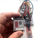
Step 2: Assembling the Electronics

The photo shows the end result, before replacing the cover.
The electronics comprise up to 3 parts:
- The Arduino and Neopixel ring
and if you are using an existing 12V AC mains adapter:
- 1N4004 rectifier diodes and smoothing capacitor
- DC-DC step-down regulator.
I will describe each in turn, but first, consider how you are going to mount them in order to fit in place of the bulb.
I soldered a 3-pin-wide piece of pin strip with the middle pin removed to the bottom of a piece of stripboard. This fits into the bulb socket.
I ensured that the stripboard was the same height as the bulb, and that the top of the stripboard was the same width as the bulb diameter. That way the stripboard could directly replace the bulb, retained at the top with the ring that used to retain the bulb.
Step 3: The Arduino and Neopixel Ring


If your Arduino comes without the pin strips ready soldered you can mount it directly onto the stripboard, by running short lengths of bare wire through the pins on the Arduino and through the stripboard, soldered on both sides. The Arduino Pro Mini needs a 6-way pin strip soldered to the serial port pads for programming.
You only need connect the +5V, GND and D8 pins on the Arduino, but cut the tracks on the stripboard between the two row of pins anyway, for safety. That will allow you to solder one or two more pins to secure it without creating any short circuits.
I used 3 pieces of thick copper wire to both support the Neopixel ring and to connect it to the stripboard.
The Neopixel ring has 4 connections: Vcc, Gnd, D-In and D-Out. We only use the first 3 of these.
Having mounted the Neopixel ring as shown, use short lengths of connecting wire to connect Vcc to the Arduino +5V pin, Gnd to the Arduino Gnd pin, and D-In to the Arduino pin D8, or D1 if you are using one of the ATTiny85 boards.
Check to ensure the stripboard conductors you soldered the Neopixel ring to don't make unwanted connections with the Arduino, and cut them if necessary to break any such connections.
Step 4: The Power Supply


If you're using a 5V power supply all you need do is connect the positive connection to Vcc/+5V and the negative to Gnd on the Arduino and the Neopixel ring, and you can skip forward to Programming.
The 12V AC supply first has to be rectified with 4 diodes (turning into DC), then smoothed with an electrolytic capacitor.
I mounted the diodes and capacitor on the same piece of stripboard as the Arduino. In the photos, the copper strips run vertically.
Mount the 4 diodes as shown, alternate ways round. The positive end of each diode is marked with a white band. Cut each of the 4 copper strips between the two ends of each diode.
The 12V AC comes in through the white wires from the pins which plug into the bulb socket. At the AC end, the diodes are connected in adjacent pairs as shown by the white lines, each AC input wire going to one positive end and one negative end of a diode.
At the other end the diodes are connected with positive ends together (red lines) and negative ends together (blue lines).
Solder the capacitor to the strips marked red and blue. I soldered it further up the board then bent the leads to allow the capacitor to sit neatly over the diodes.
Very important: one side of the capacitor is marked negative (with minus signs). You must connect that to the strip marked blue!
Now you can connect the red and blue to the positive and negative inputs respectively of the DC-DC step-down converter.
If you're using a step-down converter with adjustable output, be sure to measure the output voltage with a multimeter and adjust it to 5V before going any further or you may damage your Arduino and Neopixel ring.
Finally, connect the positive and negative outputs of the converter to the Vcc or 5V and the Gnd on the Arduino and Neopixel ring.
You may be able to mount a small DC-DC converter on the stripboard with the other components, but mine was too big, so I had to connect it with flying leads and tie it to a couple of convenient posts.
Step 5: Programming
If you don't already have it, you need to download and install the Arduino IDE. It's free. Make sure you have the latest version (1.6.13 or later - some earlier versions contain bugs which wasted a lot of my time).
In your Arduino folder (by default under Windows this is in My Documents) create a folder called Neopix_colours3. Copy the file Neopix_colurs3.ino into this folder.
Now launch the Arduino IDE and locate the sketch Neopix_colours3 in your sketchbook.
If you are using an ATTiny85 board there may not be room for the full sketch. Comment out the definition of FUNCTION_1 or FUNCTION_2 near the start of the sketch. Alternatively you may be able to squeeze the whole sketch in if you sacrifice the bootloader and program it using another Arduino.
Under Tools, select the board you are using (Pro Mini or Nano, or whatever). If you are using the Pro Mini, connect the FTDI adapter to the Arduino (make sure it's the right way round) and plug it into a USB port on your computer. In the case of the Nano you simply connect it to your computer with a USB cable.
On your computer, go into Device Manager - ports (COM & LPT) and check which COM port has been assigned to the Arduino. Set this under Tools - Port.
You can now upload the sketch and check that it works. The Neopixels are very bright so it's a good idea to place a sheet of paper over them to protect your eyes, or to temporarily change the definition of BRILL in the sketch from 255 to 50.
The sketch as I've uploaded it starts with program 1 and then switches between the two programs randomly every 5 - 10 minutes. If you prefer one or the other, find the line
function = 1;
at the end of the setup() function. Replace the 1 by -1 or -2 to lock it into program 1 or program 2. You can change the minimum and maximum times (in milliseconds) each program runs for by finding and altering the definitions of MINCHGTIME and MAXCHGTIME.
When you're happy, put everything together again, sit back and enjoy!
Attachments


Participated in the
Arduino Contest 2016

Participated in the
Make it Glow Contest 2016


