

Introduction: First Order Stormtrooper Thermoformed Mask


This Instructable will show you how to make a “Thermoformed First Order Stormtrooper Mask”, using: the Autodesk 123D Make App, a Full Spectrum H-Series 5th Gen CO2 Desktop Laser and a Homemade Thermoforming Machine.
Note - Please refer to my Instructable: “Thermoforming Machine” for the instructions to make this machine (Instructable in progress).
Step 1: Materials and Supplies Needed:
- ⅛” thickness MDF sheet - 1 Pcs, 8’ x 4’.
- White glue as needed.
- Bamboo skewers - 3Pcs.
- Wood filler as needed.
- 0.020” gauge polystyrene sheet.
- Scissors.
- Black permanent marker.
- Grey permanent marker.
Step 2: 3D Model


Attached you will find the original .obj 3D model of the First Order Stormtrooper. This original model was acquired using an “Structure Sensor” and the “itSeez3D” App for iPad, the model itself was a 48” Stormtrooper Action Figure scanned in a toy store.
The original model was edited (scaled, moved, rotated, settled and splitted) to get the mask model only. This model was edited using the “Microsoft 3D Builder” App.

Step 3: Autodesk 123D Make App Processing


- Import the mask .obj file into the Autodesk 123D Make App.
- Set a new customized material for your MDF sheets that measures 20” x 12” x 0.100”.
- Select “mm” as the object units.
- Click on the “Original Size” option.
- Select “Stacked Slices” as the “Construction Technique”.
- Set “Automatic Dowels” with Round Shape and 3mm diameter (approximately).
- Set the “Slice Direction” horizontal, parallel to the flat back of the mask model.
- Review and understand the “Assembly Steps”.
- Select “Nested” as the “Layout Arrangement”, this will allow you to minimize the quantity of MDF sheets needed to build the model.
- “Get Plans”, select “DXF” as the “File Type”, “in” as units and click on “Export”. All the “.dxf” sheets generated will be exported in a “.zip” folder. Extract All the “.dxf” files from the “.zip” folder.
Step 4: Slices Drawings Edition With Autodesk AutoCAD


- Open each “.dxf” file using Autodesk AutoCAD.
- In the file draw 4 corners 0.5” long at each side.
- Move the 4 corners over the 4 corners of the “.dxf” file.
- Erase the blue 20” x 12” rectangle. You will keep the 4 small corners as a reference to keep the original drawing extents.
- Rotate 90 degrees All the objects in the file, to set the All the objects in a “Landscape” arrangement.
- Turn Right the red knob to turn on the H-Series 5th Gen CO2 Desktop Laser.
- Push the “Home” button for the machine to set the origin coordinates.
- Open your “Full Spectrum Laser Retina Engrave 3D” App. As you have previously turned on the laser machine and set it to “Home”, then the dialog at the bottom left corner has to show: “Connected XXX.XXX.XXX.XX Homed”.
- Go back to AutoCAD and plot the file as follows: Select “Full Spectrum Engineering Driver” as the Printer/Plotter. Select “FSL Hobby Series Gen5 20x12” as the paper size.
- Select “Extents” at the “What to plot” box.
- Check on the “Center the plot” option.
- Un-check the “Fit to paper” option.
- Select “1:1” at the “Scale” box.
- Click on the “Preview” button. The result should look similar to the picture attached.
- Click on the “Plot” icon.
Step 5: Full Spectrum Laser Retina Engrave 3D App Parameters


- Now the first sheet with slices should be shown at the “Full Spectrum Laser Retina Engrave 3D” App. The result should look similar to the image attached.
- Notice that the file shown in the “Full Spectrum Laser Retina Engrave 3D” App show 3 different colors as follows:
- Red – For the parts ID numbers and reference contours. The objects in this color will not get cut but engraved only.
- Blue – For the parts external contours. The objects in this color will get cut.
- Black – For the reference corners added. These corners will not get cut nor engraved.
- Set the “Vector Layers” parameters as follows:
- Red – Speed = 100, Power = 5, Passes = 1
- Blue – Speed = 30, Power = 65, Passes = 1
- Black – Speed = 100, Power = 0.01, Passes = 0
- Please note that the effectiveness of these parameters to appropriately cut and engrave the material, may be affected by the lens conditions (cleanliness and alignment) among others.
Step 6: Using the Full Spectrum H-Series 5th Gen CO2 Desktop Laser


- Place one of the MDF sheets over the Honeycomb base.
- Move the laser head with the control arrows to any point where the circular bottom part of the head gets “completely projected” over any section of the MDF sheet.
- Check what “Focus Lens” is installed in the laser head. In my case, I am using the 1.5” Focus Lens.
- Pick the corresponding “focus cylinder”.
- Loosen the focus fixing screw to allow the adjusting head move up and down freely.
- Place the “focus cylinder” between the MDF sheet and the laser head.
- Let the bottom of the adjusting head get in touch softly with the top of the focus cylinder.
- Tighten the focus fixing screw to fix the position of the adjusting head and remove the focus cylinder
- Done! The Laser is now focused!
- Let’s get the MDF sheet properly aligned and positioned in the machine:
- Move the laser head to the top left -20,0 position.
- Make the red dot laser lay inside (about 1/16” inside) the MDF sheet top left corner.
- Move the laser head to the -5,0 position.
- Make the red dot laser lay inside (about 1/16” inside) the MDF sheet near the sheet top edge.
- Done! The MDF sheet is now aligned!
- Turn On the cooling water pump, the air compressor and the fumes extractor.
- Set the laser head to the top left -20,0 position.
- In the .“Full Spectrum Laser Retina Engrave 3D” App click on the “Start Job” (Play) icon to start cutting the fist sheet with slices.
- Repeat the “Autodesk AutoCAD” plot process for every one of the sheets generated and then cut them using the “Full Spectrum Laser Retina Engrave 3D” App and the “Full Spectrum H-Series 5th Gen CO2 Desktop Laser”.
Step 7: Model Assembly and Finishing


- Once you get all the slices cut, it will be time to assemble the whole model.
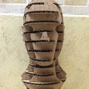
- Follow the assembly steps defined by the “Autodesk 123D Make” App. In this case you will start with the slice # 1, add glue to the upper face of this slice and then assemble the slice # 2 on top of it, continue this same process until you have enough slices to keep the dowels (Bamboo Skewers) in vertical position. Continue this process following the assembly steps until All the slices get assembled. Let the glue dry over one night. The final model should look like the image attached.
- Using a putty knife, spread the wood filler all over the model filling and smoothing the model surface to eliminate “step like” finish. Let the filler dry according to the instructions for the specific wood filler you use.
- Sandpaper the model surface, starting with a “Coarse” grade as 40, followed with a “Medium” as 100, and finishing with a “Fine” grade as 150. The resulting model after sanding is shown in the photo attached.
Step 8: Thermoforming


- Now is time to use the “Homemade Thermoforming Machine”
- This machine is basically comprised of 2 sections: One is the “heating section” and the other one is the “vacuum section”.
- The “heating section” uses a cavity insulated with fiberglass and galvanized steel sheet. The cavity is heated by 2 heating elements (charcoal starters) controlled by 2 dimmers that controls the temperature and a thermocouple attached to a digital multimeter to read the “heating section” temperature.
- The “vacuum section” is a chamber with small holes distributed all over the top surface, and with a suction aperture on its side to attach a vacuum cleaner to it.
- This Thermoforming machine is used to shape a plastic sheet with help of a mold (sanded slices model) to do so.
- The operation sequence is as follows:
- The plastic sheet (0.020” gauge polystyrene sheet) is trapped between the 2 frames.
- The trapped plastic sheet is placed on top of the heating cavity.
- The temperature reading is allowed to reach around 480 degrees F.
- The hot plastic sheet including the 2 frames are moved manually above the mold that is placed over the vacuum bed.
- The vacuum cleaner is turned On immediately and the thermoformed sheet is allowed to cool down.
Step 9: Finish


- Remove the Laser machine floor.
- Cut two 0.5" diameter holes (at the eyes area) as means to see thru the mask.
- Cut the excess of material on the edges using scissors.
- Detail the mask using the permanent markers.
- Have Fun!

Participated in the
Full Spectrum Laser Contest 2016


