

Introduction: First Person View RC Robot!


We created this little RC robot for the first Ohio State University MAKEathon this year. We determined we wanted to make a FPV robot before the competition, but the concept generation, modeling, coding, wiring, printing and assembling all took place at the MAKEathon. We managed to complete it all within the 24 hour time limit!
The members of our team included:
Nate Duxbury (me)
Ryan Stutzman (co-authored this instructable)
Aaron Maharry
Brent Niese
We had a lot of fun with this project, both with making it and playing around with it afterwards. Hopefully anyone following this instructable will have as much fun too!
Step 1: Parts List


Tools Required:
Soldering Iron
3D Printer
Computer to program the arduino
Heat gun (or lighter, or just the barrel of the soldering iron)
Hot Glue Gun and hot glue
Components required:
QTY 1 Spektrum DX6i Radio transmitter (http://amzn.com/B00K1P3KYW)
QTY 1 Fatshark FPV System (http://amzn.com/B00I08F7UM)
QTY 2 parallax continuous rotation servos (http://www.microcenter.com/product/440945/Continuo...
QTY 1 parallax Standard Servo (http://www.microcenter.com/product/390016/Standard...
QTY 1 small standard servo (http://amzn.com/B001CFUBN8)
QTY 1 Arduino Nano
QTY 1 5V Regulator
QTY 1 Li-ion Battery Pack (with appropriate connectors soldered on)
QTY 1 M5x50mm Screw
QTY 1 M5 Hex Nut
QTY 6 Rubber Bands (approximately 2-2.5" diameter, .25" width)
Various small screws and washers (I used screws taken from old nerf blasters)
Various headers, both male and female
Heat Shrink
Zip Ties
Printed Parts Required:
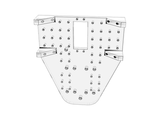
QTY 1 Base Plate
QTY 2 Wheel
QTY 1 Camera Pan Bracket
QTY 1 Camera Tilt Mount
QTY 1 Roller ball
Step 2: Print the Parts
Just like the title says, print the all the required printed parts. Refer to the previous step for how many of each of the printed parts you need. All the parts can be printed with low infill percent (I used 15%) and a fairly coarse layer height (I used .35mm). I recommend printing the camera gimbal parts first, so that you can assemble them while the rest of the parts are printing.
Print times for each part are as follows (approximate):
Base - 4 hours
Camera Ban Bracket - 45 minutes
Camera Tilt Mount - 25 minutes
Wheels - 2 hours each
Roller ball - 25 minutes


Step 3: Assemble the Camera Gimbal


If you printed the camera gimbal parts first, you can start on that sub-assembly while the rest of the parts are printing.
To begin, you'll need to remove the support material in the camera pan bracket. The pocket for the servo horn and the center mounting hole will have support in them, so drill out the hole and clip away the center line supports. It doesn't have to be perfect, but it does need to be cleared enough for the larger servo horn to fit. Once the support is cleared away, use hot glue to mount the servo horn, making sure to keep any glue out of the splined center hole.
Take the small standard servo and insert it into the square cutout in the camera pan bracket. Screw it in with at least one of the mounting holes. The servo hub should be positioned so that it is furthest away from the bottom of the bracket (check the exploded view).
Next, Insert the Fatshark Camera module into the camera tilt mount. Make sure that the camera is oriented correctly, when looking at the rear of the camera module, the text should be facing upwards when the cutout for the tilt servo horn is on the right hand side. Insert the camera module into the stepped down area and zip tie it into place with two straps (one on each side of the lense).
Then, insert the servo horn for the smaller servo into the camera tilt mount using hot glue. Make sure to not get any glue into the splined hole where the horn attaches to the servo or you won't be able to mount it to the servo correctly.
Take the (camera) + (camera mount) + (servo horn) sub assembly and attach it to the small servo (which should already be installed into the pan bracket). Insert a screw through the hole in the pan bracket and screw it into the hole in the camera tilt mount.
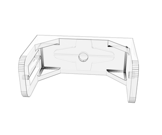
Step 4: Assemble the Frame

This is exactly what the title of this step says...assemble the frame. This is where you fasten the continuous rotation servos and the camera gimbal into the frame.
The continuous rotation servos should fit right into the brackets that are printed with the base plate. Install them with the servo shaft closer to the front of the robot (the wires of the servos should be coming out this side as well). Screw the servos in with at least two small screws each (optionally, use all four screw holes that the servos and brackets have available).
Installing the camera gimbal is much the same. With the servo shaft and wire facing the front of the robot, put the standard servo into the rectangular cutout for it. The mounting bracket of this servo should be on the underside of the frame, the same side as the drive servos. Again, screw in with two to four screws.
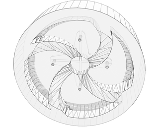
Step 5: Assemble the Wheels


The wheel Sub assemblies are very simple.
Start out by removing the support material inside the servo horn cutout on the wheels. Same as before, drill out the hole, and then clip away the center line supports. Once cleared, hot glue the standard size servo horn into the pocket. Make sure not to get any glue inside the central hub area, or you may have trouble installing it onto the servo.
Next, take three of the rubber bands and wrap them around the printed wheel. The rubber bands help the otherwise smooth printed wheels get a little grip, and at least in our case, added some color.
Repeat these steps to make the second wheel.
Step 6: Electronics and Wiring

There are quite a few electronics in this project. The main electronics are the Arduino, RC transmitter/receiver, and the FPV system. The battery that we used was a 3S LiPo battery. This is a 11.1V and 1,300mAh battery and I estimate it allowed for approximately 30 minutes of continuous use of the robot. You could really use any battery you want to use, but it needs to be at least 6V. This is due to using 5V linear regulators. In order to get 5V out of them you need to supply them with at least 6V.
As far as connections go, there are quite a few of them. To start things off, we need to connect the power to the robot. Since I used a LiPo battery, I had 2 power plugs that I could use. I used the balancing plug to power the FPV transmitter and the charging plug to power everything else. The battery is located under the main body so you have to run wires from the top of the body through a hole to get the battery. Once that is done the ground from the battery will go to the Arduino, the RC receiver, and the 5V regulator. The hot wire goes to one pole of the switch beside the Arduino. The other pole will have a connection to the Vin on the Arduino and to the Vin on the 5V regulator. The next and last power connection is from the Vout on the 5V regulator going to the hot pin on the RC receiver.
Next is connecting the servos. The way that you connect the servos to the RC receiver will depict which gimbal on the RC transmitter controls the camera gimbal on the robot and which one controls the robot's movement (forward, reverse, turn left, and turn right). The way I had it set up was to use the left gimbal on the RC transmitter to control the pan/tilt on the camera gimbal. This would require the tilt servo to be connected to the throttle on the RC receiver and the pan servo to be connected to the rudder on the RC receiver.
Now your battery and camera gimbal are connected and set up. If you would like to test the camera gimbal on the robot, this would be the time to do it.
Next is connecting the wheel servos. This is the tricky part. You can't directly control these servos with just the RC transmitter/receiver while using only one gimbal on the transmitter. We'll look at how that's set up in the next step.
Step 7: Programming Logic and Arduino Sketch
In order to control the movement of the robot by using only one gimbal of the transmitter, you have to use a secondary device to process the values the RC receiver outputs. This is where the Arduino comes into play.
Both wheel servos should have their power connected directly to the RC receiver, but the signal wires get connected to the Arduino. The first connection is the elevator signal pin on the RC receiver gets connected to digital pin 7 on the Arduino. Then the aileron signal pin on the RC receiver gets connected to digital pin 8 on the Arduino.
Next is connecting the servos to the Arduino. The left wheel's servo signal wire gets connected to the Arduino's digital pin 10. The right wheel's servo signal wire gets connected to the Arduino's digital pin 11.
Now all that's left is to connect and program the Arduino. The program that I used is attached to this step.
With using continuous servos, you may have to adjust the trim on the servos. This would be the case if you are not giving the robot any throttle, yet the servos are moving. That's what happened to me. I thought it was my code to begin with, but then I figured it out and adjusted the trim. BAM! Everything now works as expected.
Attachments

Step 8: Final Assembly


Everything is coded, and all the mechanical parts and sub assemblies should be ready at this point. Now all that remains is to assemble it all together and then its done!
Begin by taking the frame assembly (completed earlier) and installing the wheel sub assemblies onto it. This should only require light pressure to attach the servo horns (now embedded in the wheels) onto the servo shafts.
Next, take an M5 hex nut and press it into the "roller ball" printed part. It should be a friction fit, but if not, give it a little hot or super glue, taking care to keep any glue out of the threads. Take the M5 Screw, and thread it through the hole near the rear of the frame (the head of the screw should be on the top side of the frame), and then screw the roller ball with hex nut onto the bottom of the screw. The robot should now be balancing on the two wheels and the roller ball!
After that, its time to install the electronics board. We used a piece of perf board sized roughly 1.4"x4.2". This board should contain the 5V regulator circuitry, the arduino nano, a switch and the control receiver module. The reciever module can be zip tied down to the board by slightly drilling out a few of the holes. The switch is easily hot glued into position, and the arduino and 5V regulator circuitry is soldered to the board. The electronics board needs to be mounted on some kind of stand-offs, which could be easily printed or made from anything laying around. Hot glue the four stand offs to the corners of the electronics board, and then hot glue the other side of the stand-offs to the frame.
The final thing to be assembled is the FPV transmitter board and the battery. The FPV transmitter is mounted on the top side of the frame, and the battery is mounted directly below it on the underside of the frame. These two components can be zip tied in tandem with each other using the holes in the frame.
Step 9: Controlling, Testing, and Usage!
Congratulations! You're finished! This is where you finish testing and, if everything works correctly, start having fun driving the robot around.
For our setup and wiring, the left stick on the transmitter controlled the pan/tilt function of the camera gimbal and the right stick controlled all the driving. While not setting any land speed records in the straight away, this little bot can turn very quickly with little to no radius.
Another thing to note, is that you must have the transmitter on before you flip the switch on the bot. If you do not, the drive servos will start to move on their own! Likewise for powering down, make sure to flip off the bot switch before turning off the transmitter or you'll get the same behavior.
Also, be careful when using it for too long! There is no voltage sense circuitry on this bot, and when LiPo battery discharges too much, it may be difficult to get it to charge properly again. The thing to look for is especially sluggish drive speed. When this starts happening, the voltage in the LiPo has most likely dropped far enough that you should stop and charge it.

Participated in the
3D Printing Contest

Participated in the
Mind for Design

Participated in the
Move It


