

Introduction: Footswitch Operated Sandblasting System


My (ex-wife) has a sandblasting setup that she bought about 2010 to start her own business. She does mostly glass engraving but wanted to also be able to do wood and stone products. The grit that she uses is very expensive and would be ruined if it was used for wood so for her to switch over, she had to completely drain the cabinet and pressure pot, clean everything, then refill and re-calibrate for the new medium. This process was very time consuming, so we considered getting a new system just for the wood and stone items. The company wanted about $1,500 to $4,000 for a new system which I thought was completely unreasonable.
This is the arrival of the first system... it is huge!
After looking online at Harbor Freight, we found a nice medium cabinet and a good sized (110lb) pressure pot for a very reasonable price... then they BOTH went on sale. For less than $500 we could purchase both... I just needed to convert the pressure pot to run with a footswitch.
I called the company who would be happy to sell me just the footswitch for $90, the pinch valve for $130, and the bladder for $35. It was time to hit Amazon to see if I could do better... I found an even better footswitch for about $30... 1/3 the price!
I used the Model FV320 Foot-switch, 3 Way, 2 Position
UPDATE: I seem to get a lot of people trying to do this who buy a 2-way foot-switch... this WILL NOT work. To operate the PINCH VALVE, it needs pressure applied all the time... then when you step on the foot-switch, the pressure is REMOVED and the pinch valve releases air through the foot switch to the atmosphere allowing it to deflate and pass the air-grit mixture from the pressure pot. If you install a TWO-WAY valve... it will apply pressure ONLY when stepped on... and that means the system will blow grit...UNTIL... you step on the foot-switch... then air will flow into the bladder and stop the grit. However... when you remove your foot... the valve stops... but the air in the bladder cannot escape... so the valve remains shut until it finally bleeds out and opens. (Usually when you DO NOT want it to!)
Now I needed to get the pinch valve assembly, the original company wanted $250 for the conversion kit... I thought I could do better. After some research, I found the exact replacement assembly from a company called Airpinch. (They were very helpful too.)
Step 1: The Pinch Valve - the Key to Using a Footswitch Control


A pinch valve is a housing with a bladder made from rubber, silicone, or other material based on the substance you wish to control. Since this was going to control a very abrasive material, durability was highest on the list. After a quick phone call, I was able to get a part number for exactly what I needed... a 3/4 inch pinch valve, made from glass filled nylon (black), and with a bladder made from BUNA-N. I got the whole assembly with an extra bladder for under $100... much cheaper than what the other company quoted me.
UPDATE: The company said not to buy a spare... they get hard/brittle over time... so only order one when you need it.
Use these part numbers if you want to duplicate what I have... (2015 Pricing)
AP-6798 Pinch Valve Assembly (AT-06-NF-B60-0606-N) $62.00
AP-6277 Replacement Bladder (AT-S-06-NF-B60) $22.50
Total Cost: $82.00
The original system was set up as shown in the image below. The main tank has 120 PSI that is regulated to 90PSI and distributed to the workshop. This is regulated to 40 to 60 PSI for the pressure pot... more likely 40 PSI. That meant that the bladder assembly was getting the full 90 PSI from the system. After talking to the folks at Airpinch, they said it should only be about 20 to 30 PSI above the pressure of the substance it was controlling, or the life of the bladder would be shortened. They said that a second regulator should be installed to lower the pressure to about 65 PSI if I was running the pressure pot at 40 PSI. The original system did not have this second regulator... it was running between 90 and 100 PSI... so this would be addressed in the new design.
I also did not like that the plumbing stuck out from the pressure pot about 25 inches or so... it seemed to be asking for trouble if something bumped into it. I decided to mount all the regulation and switching valves on the wall to keep them in an area less likely to come into contact with anything. This would also have the added benefit that we would not need to lean over, and we could see the pressure settings as we worked... something we could not do with the current setup.
Step 2: The System Design - Figure Out How It All Works


The first image shows the design layout for a footswitch control system, the second another view without the main compressor. The regulated air comes in at 90 PSI and runs through a water trap to remove any moisture that could have a bad effect on the grit. (It could cause it to clump or jam up in the hoses.) After the water trap it is split into two paths, one to the pressure pot and nozzle assembly, and the other to the footswitch control.
The first path goes through a regulator to get the 40 PSI for the pressure pot, it then goes into a splitter where part keeps the pot under pressure, and the other passes below to a mixing valve where it picks up grit and passes through the pinch valve. From there it heads to the sandblasting nozzle. The Harbor Freight pot has two valves that are normally used to control it when you don't have a footswitch control. I left these in place, but if I were to do it again... I would use them on the manifold and save the $7 each for the ones I got at Lowes. (Because of the footswitch assembly they are no longer needed where they are currently mounted.)
- - - - - - - - - - - - - - - - - - - - - - - - - - - - - - - - - - - - - - - - -
UPDATE: It seems NOBODY reads this section...
you need a THREE-WAY foot-switch!!!
The CORRECT way to connect it is so that the air pressure is connected to what is normally the vent port... with the pinch valve connected to the OUTPUT port. This way... air from the compressor is NORMALLY pressurizing the internal bladder of the pinch valve. (All the time.) Then... when you step on the pedal... the air is SHUT OFF and the residual pressure in the pinch valve bleeds out to the now OPEN port.
Yes... backward from how normally connected.
Otherwise... IT IS NOT GOING TO WORK!!!!
- - - - - - - - - - - - - - - - - - - - - - - - - - - - - - - - - - - - - - - - - - -
The foot-switch needs to supply the bladder port with a constant pressure, then when you step on it, the bladder needs to be able to vent out. Normally the foot-switch is used with the IN and OUT ports to control a pneumatic cylinder or similar device, the VENT port would just bleed air into the room. In this application however, the air is fed into what is normally the vent. The other fittings were 1/4 inch, but the vent is an 1/8 inch fitting... so after another quick trip to Lowes ($7)... the foot-switch was ready to go.
Step 3: Modify the Pressure Pot


The Harbor Freight pressure pot comes with a cast metal fitting that connects with the top valve and acts as a mixing chamber. (Image 1 and 2) If you look at the original sandblasting setup (Image 3) you can see it is completely different. This is what we needed to build into the new system to make the footswitch work properly.
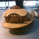
In image 4 you can see how the pinch valve assembly is being put together. We decided that we might need to blast a larger wood item in the big cabinet, so we also installed hose fittings on each of the pressure pots. This way we can simply switch the nozzle assemblies and clean out the cabinet without needing to purge the pots. (Changing out the grit in a pressure pot is a MAJOR chore!)
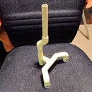
Image 5 shows one of the disconnects during assembly, and image 6 is after assembly is completed.. The tool on the bottom has been around since World War II... some people say I should not use it... but I feel a tool is meant to be used... and I use this one a lot! (I've never seen another like it.)
The last two images show the finished pinch valve assembly mounted to the pressure pot, and the original pressure pot (white system) after it has been stripped down and configured the same way. Now we have two interchangeable pressure pots that can be used with either cabinet. Because they just happened to already be painted as they are... we call them the WHITE and the RED systems. The RED system is the newer one for working with stone and wood.
Step 4: Finishing Up


Once the pressure pots were modified, the only step left is to connect them through the regulators so that they can be used. We have two systems with two pressure pots... so in the following images you will see a duplicate set of valves for the pots, and another duplicated set for the foot pedals. In a single system these extra ports would not be needed.
The white system is the original sandblasting setup, the red system is the new Harbor Freight system that has been modified for the foot switch. To use the system it is important to turn the valves on and off in order... if you were to turn off the supply first for example... air could be sucked in from the pressure pot... along with the grit... and pas backward through the pressure regulator. This would damage or destroy the regulator.
Normal activation of the new red system would be like this...
1) Turn on main air supply. This feeds clean 90 PSI into the system to the regulators through the water trap.
2) Set the regulators (top) for 40 PSI, and (bottom) for 65 PSI. This sets the system to the correct pressures.
3) Open the RED pedal valve. This causes the pinch valve to close preventing the system from spraying grit all over.
4) Open the RED pot valve. This causes the grit pot to pressurize.
UPDATE: The foot-switch needs to be 10-20 PSI HIGHER than the pot... otherwise the pinch valve can't close!
Of course... be sure the lid is screwed down well... you don't want it to do a grit volcano in the workshop! And before you pressurize the system... ALWAYS WEAR A MASK!!!
You really don't want to breathe this stuff... so again... ALWAYS WEAR A MASK!!!
Shutdown is pretty simple...
1) Turn off the pot valve.
2) Turn off the pedal valve.
3) Turn off the main air valve.
4) Step on the pedal to allow the system to bleed down. Some grit will escape.
If you don't want any grit to get out... you could close your grit mix valve at the bottom... but usually it's more trouble than it's worth.
The last image shows the Harbor Freight pressure pot valves. It also has a secondary water trap that automatically vents when the pressure drops below about 15 PSI. It is actually better equipped than the $900 pressure pot that she got with the system. The image also shows the two valves that are no longer being used... they could be used on your system as the pot and pedal valves. You would just replace them with a standard pipe fitting.
I hope this helps you to set up your own system, we completed the entire project for about $600 including the cabinet, pressure pot, and all the plumbing for the air supplies. It cost us less than what the pressure pot alone would have cost.

Participated in the
Fix & Improve It Contest

Participated in the
Hurricane Lasers Contest


