

Introduction: From Candy Boxes to Proto Boxes


I salvage electronics for parts and projects and I like clear proto boxes to put my projects into, that way I can show off my work. I can never find proto boxes in the store when I want one, let alone clear proto boxes that let me see the internal components until one day I spotted some candy in the store.
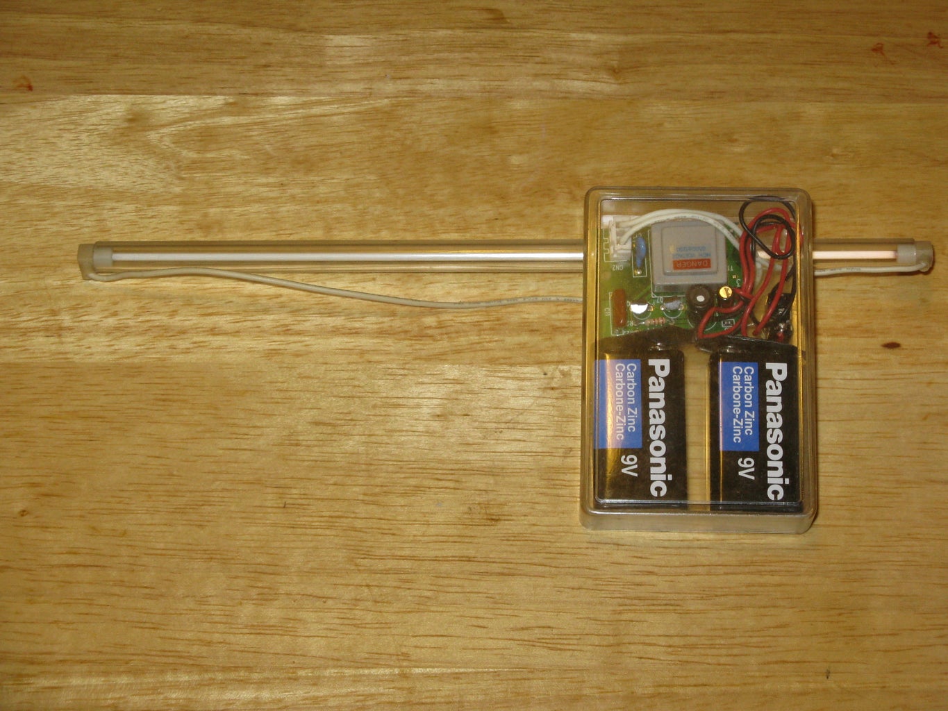
I can just imagine how conductive paint would improve a project like this, my latest creation is a signal generator, and instead of running wires I could paint the wires on the plastic.
This project is a green project because of the salvaged circuits and the reuse of candy boxes.
Step 1: The Candy Boxes

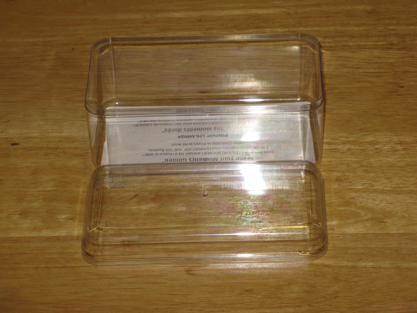

These candy boxes from Ferrero Rocher are designed to show off the candy and they make great proto boxes coming in a variety of sizes just the right dimensions for small circuits and other components. The best part they cost less than a proto box and you get a treat.
My wife thinks I am a romantic giving her chocolates all the time, now she knows I want the boxes but she still likes getting the Bon Bon’s. I open one of these boxes of Bon Bon’s and before I can say Bon Bon’s their gone between my wife and sons, I am lucky to get one.
Step 2: The Signal Generator

My wife got me this signal generator circuit from Canada Kit, as my Christmas gift. The circuit is based on a Wien-Bridge oscillator, which provides a sinusoidal output in a sine and square wave in the audio frequency range. It is also an instructional tool that can be used to display waveforms on an oscilloscope.
It has two independent outputs, one for sine wave and the other for square wave. The circuit can produce frequencies from approximately 40Hz to 2.5KHz or from 2.5KHz to 10KHz depending on the position of the range select switch. The sine level can be adjusted from 0 to 2V peak-to-peak through a trimmer potentiometer. The square wave output provides two separate fixed level outputs, one at 5V and the other at 9V.
Step 3: Modifications to the Circuit

The signal generator circuit kit from Canada Kit was not preassembled so it was easy to add a switch to turn the circuit on and off and a switch I could I could mount to the proto box to change the frequency range without opening the proto box.
Step 4: Selecting the Box


The boxes I have to choose from are:
6 x 2 ½ x 2 ¾ inch sharp edged
5 ½ x 3 x 2 ¾ inch diamond edged
5 ½ x 3 x 2 ¾ inch round edges
6 ⅜ x 4 ⅜ x 1 ½ inch sharp edged diamond patterned
I have a number of projects to mount in boxes and for the Signal Generator I needed a box large enough to house the circuit with room to accommodate lining up the pots for making the holes.
It had to house the battery and needed room on one side for the two switches and two pots. I would have preferred a box that had room for the outputs also but I can put the outputs on the top of the box.
The box I selected was the 5 ½ x 3 x 2 ¾ inch round edged.
Step 5: Mounting the Circuit


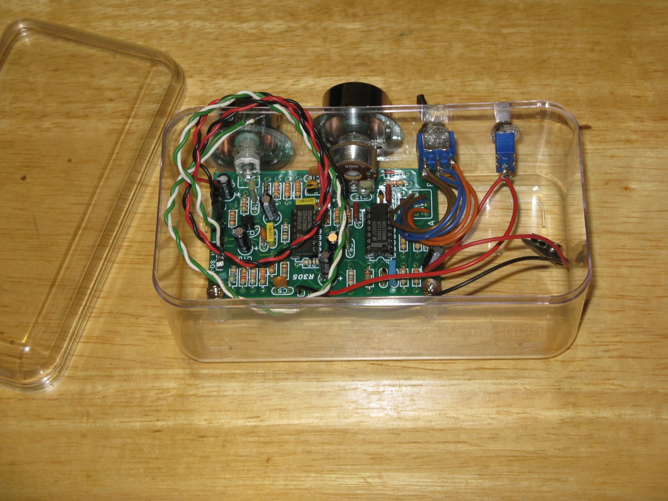
Start by mounting spacers on the circuit and placing the circuit board inside the box.
Mark the front of the box where the pots will go.
I used a soldering Iron to make the holes for the pots then I removed the front two mounting spacers and bolt the circuit to the front of the box by the pots.
On the bottom of the box I used the soldering iron to make the holes for the back mounting spacers and screwed them to the box.
Last I made the holes for the switches and mounted them to the front of the box.
Step 6: Mounting Feet on the Box


On this box the screws in the back mounting spacers jut out making the box unstable so I added feet to the bottom of the box.
You can buy stick on feet or you can make feet and glue them on the box, just as I did in this Instructable I made feet from cork and glued them to the bottom of the box.
Step 7: Connecting the Output Terminals


I would have preferred matching red, black, white, and a green output terminals to distinguish the different out puts, however the only matching terminals in my parts are red and black.
With the soldering iron I made four holes in the lid of the box and bolted the terminals to the lid and connected the wires in order.
From left to right, sine, common, square low square high.
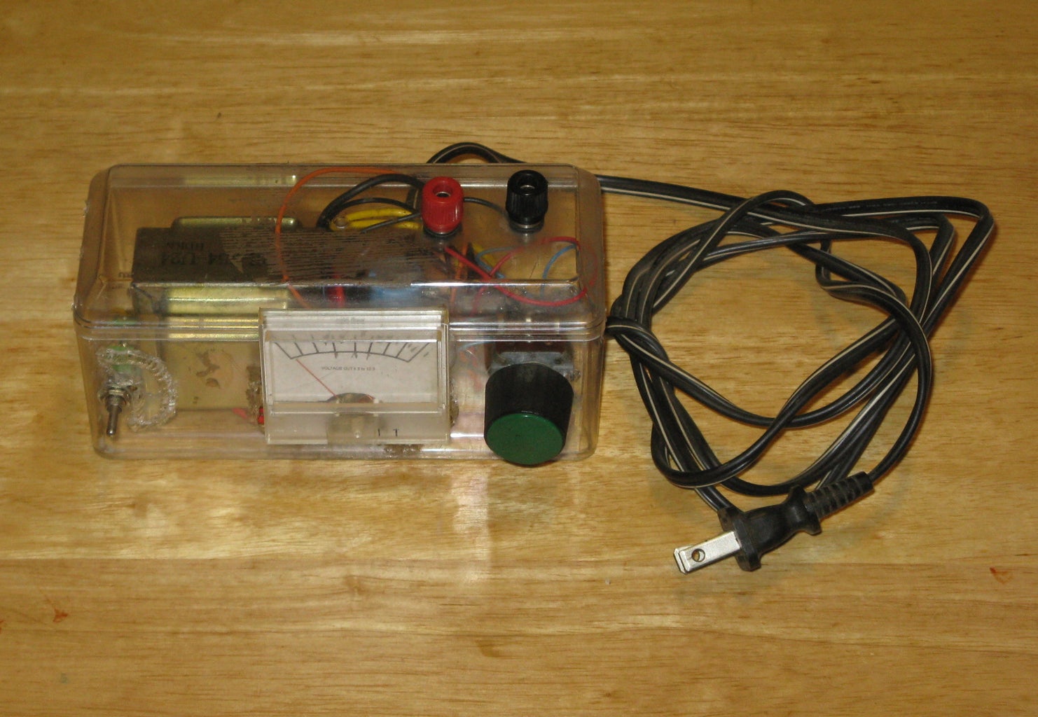
Step 8: The Finished Signal Generator


Not easy to see in the photos is the last thing to do; marking the controls and out puts, for this I used colored Mini Fonts transparencies.
I marked the on and off switch 0 and 1.
I marked the frequency range switch A and B.
I marked the pots low side with 0.
And I marked the terminals S for sine, C for common, SL for square low, and SH square high.

Participated in the
Instructables Green Design Contest

Participated in the
Epilog Challenge V


