

Introduction: From Light Bulb to Arduino (Microcontroller Getting Started)


When I was a kid, the very first basic electronics lesson delivered to me was "Light Bulb Circuit". When I went into college, LED was getting cheaper and cheaper and widely used in electronics as indicator lights and also replacing the light bulb. Yesterday, my fifth-grade boy asked me "How can those lights blink according to the music on stage?" Well, then I think I will not only teach him about LED, but also the blinking LED on Arduino.
Why light bulb? Why LED? Because kids' eyes are always attracted to glowing light sources. Light bulb circuit also be the simplest circuit to build, to learn basic electronics about voltage, current and resistance.
Well, in this project I teach my kid about the legendary light bulb circuit, the LED and resistor replacing the light bulb, then the basic programming a blinking LED with Arduino UNO.
Step 1: The Legendary Light Bulb Circuit

The simplest circuit to present to the kids.
- 2 x 1.5V AA batteries with the container.
- A 3V light bulb for flashlight.
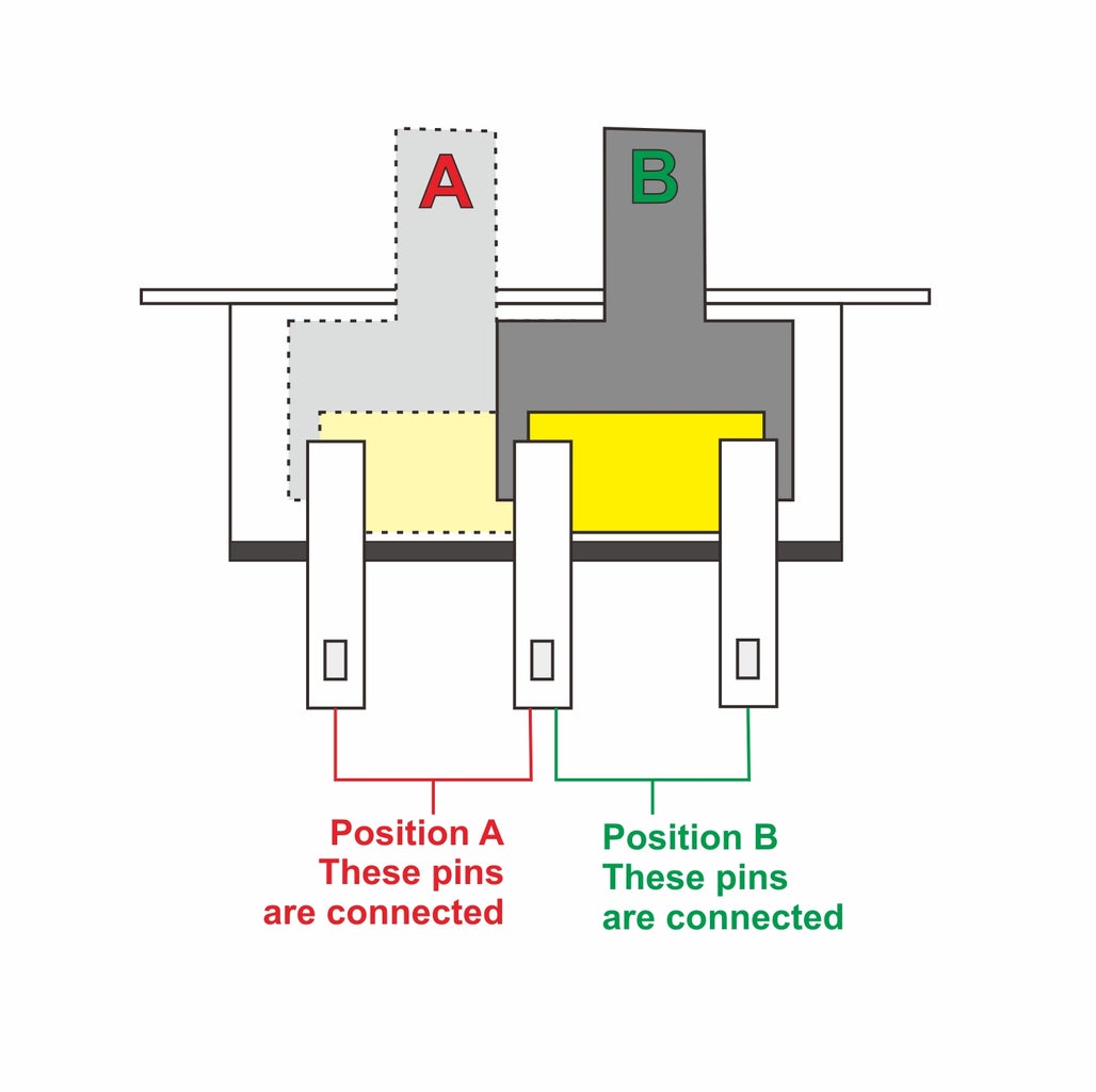
- An on/off slide switch.
For instant, you can tear down any flashlight at home to show them the parts. Of course I am not referring to those flashlight on your smartphone (-.-')
The good news is we do not need all those parts to teach our kids. Thanks to the digital world today where we can do electronic circuit simulation on the computer, one is TinkerCAD by Autodesk. Just sign up an account and find "Circuits" section. Create a circuit with clicks and drags and click on the "Start Simulation" button to get your circuit run. The interface is simple and easy to use, even for kids.
When the simulation is running, you can click on the switch to test turn on/off the light bulb to see if all the parts are properly connected. We can edit the parts' properties on the run, but we cannot edit the positions or wires. You need to stop the simulation to edit the circuits. Well, at this point I presented the simplest working circuit to my kid, the ON and OFF of light. I also explain the three-pin slide switch where there is a small part of metal connecting the center terminal to the left terminal or right terminal so we can connect one wire to the center and the other wire either on the left or right pin.
"The light is ON! Well done, Boy!"
Step 2: LED : the New Light Bulb


Now, let's change the old light bulb with Light Emitting Diode (LED). Then I add a resistor in the circuit. This is still the same as the legendary light bulb circuit before, only that the light bulb is replaced with LED plus resistor. Now I need to explain to him about LED and resistor but of course not every details.
LED is the new light bulb, it emits light when certain voltage is applied to it. LED has polarity which means current only flows in one direction. When you take a new LED, the positive lead (which is called anode) is longer and the negative lead (which is called cathode) is shorter. What if you get a used LED which has both leads trimmed? Look around its plastic body and find a "flat spot", then that is the negative/cathode lead. What if the plastic body is already broken and you have both sides flat? Then try to look inside the LED, the one with larger piece inside the body is negative/cathode lead.
Although the LED has polarity, you have no worry if you put it the wrong way. That wouldn't burn/break your LED but it just won't light up until you put it in the proper direction. Then why it needs to be paired with a colorful zebra? What? Well.. umm.. that is called a resistor.
LED has a property called Forward Votage. This is the minimum voltage required by the LED to make it glow. Usually the voltage is something between 1.7V to 3.3V. Well, the most practical power source is AA battery. But wait, AA battery is 1.5V and a single battery won't light the LED. If you use two batteries, it will glow brightly. It draws as much power available in the batteries. As a result, the batteries drain faster and consuming too much power will reduce the lifespan of the LED itself.T
We need the help of Resistor to limit the current so that both the battery and LED last longer. Resistor has no polarity. Resistor can be connected either on LED's anode or cathode. At this point, I am not going to explain to my son about the calculation, although we have online calculator handy. He wants to know the magic of illumination and I gave him that. I pick a resistor with value 150Ω to 330Ω for this project. This can be used on both 3V (two AA batteries) and 5V (arduino).
I also showed him in simulation what will happen when we increase the source voltage to 9V without resistor.

Step 3: Tell the LED What to Do

Now we tell the LED what to do, when to glow, with programmable microcontroller called Arduino Uno. In TinkerCAD simulation I added LED and resistor on pin GND and D13. I also run the sketch on my Arduino Uno and telling him that it has built-in Resistor+LED on digital pin D13.
Demonstration went on with changing the time delay and also blinking at different intervals. On the next steps let's take a brief instruction about TinkerCAD and Arduino Web IDE.
Step 4: Drag Drop Programming

Go to www.tinkercad.com and sign-up an account just like signing up an email account. I'm pretty sure you can do that with on screen step by step instruction ^_^
- Login to TinkerCAD.
- On the left sidebar, find "Circuits" section.
- Click on "Create new Circuit".
- Use your imagination to design your circuit simply drag and drop and draw wires to connect.
- When you add Arduino Uno in your project, it will automatically load the blink sketch.
- Click on "Code" on the right side of Toolbar Menu to show up the code blocks.
- Click on the "Blocks" drop down menu and click on "Blocks + Text" to see the Arduino Sketch.
Now we discover the Arduino Sketch like this :
void setup()
{
    pinMode(13, OUTPUT);
}

void loop()
{
    digitalWrite(13, HIGH);
    delay(1000); // Wait for 1000 millisecond(s)
    digitalWrite(13, LOW);
    delay(1000); // Wait for 1000 millisecond(s)
}
He loves the Chinese cartoon Boonie Bears where the main character is a logger named Guang Tou Qiang. Explaining the Arduino Sketch I gave him an analogy like this :
- void setup() is where we put all the preparation. It is like : Guang Tou Qiang put on his helmet and his axe ready to cut down trees in the wood. pinMode (13, OUTPUT); means we get digital pin 13 ready to give us light.
- void loop() is where we get the things be done over and over again. It is like : Guang Tou Qiang get his axe on his shoulder, inhale, swing the axe toward the tree, exhale, retract the axe to his shoulder, inhale, swing the axe toward the tree, exhale, and again and again until he loses power.
- digitalWrite(13, HIGH); means turn on the LED.
- delay(1000); means wait for 1000 milliseconds (1 second).
- digitalWrite(13, LOW); means turn off the LED.
- delay(1000); means wait another 1000 milliseconds before repeating the void loop() from the top.
Change the delay parameter and add another digitalWrite commands in the sketch will give the best understanding to Arduino Sketch.
Step 5: Arduino Online Editor


We may choose to download and install offline editor, but now we have online editor, why not? With online editor, all our sketches will be uploaded and saved in cloud storage. We can access to the sketches anytime, anywhere on this planet, as long as there is an internet connection available.
- Go to create.arduino.cc/editor.
- Sign-up an account if you are a new user. Just like singing up an email account.
- Login to arduino web editor with the account you have just created.
- Before using the Arduino Web Editor, first you need to follow the instruction to download and install Arduino Plugin on your computer (click here to jump to the getting started page). Follow the on screen step by step instruction.
- Once you have login to the site, you will get Arduino Web Editor on the first icon (out of six icons). Click on it to get into the editor.
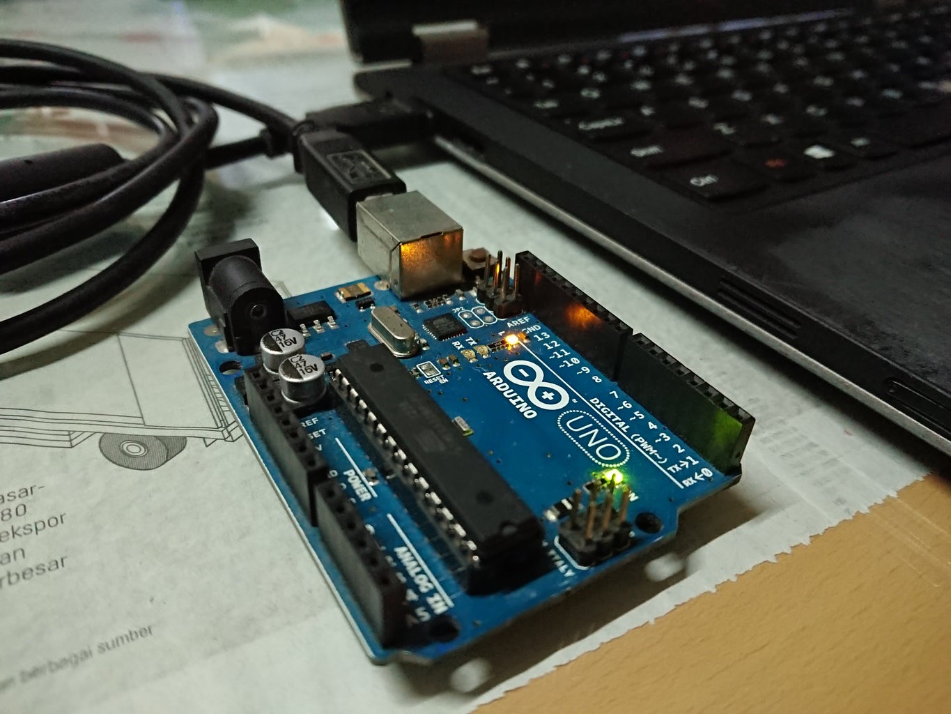
- Plug your Arduino board to one of the USB port on your computer.
- Write or copy the sketch from TinkerCAD and paste it in the Arduino Web Editor.
- Pick your board and port. The port will shows up when you have installed the plugin correctly.
- Click on "✔" (verify) button to verify your sketch.
- Click on "→" (upload) button to upload the sketch to your Arduino.
- If everything goes well, you will see the blinking TX and RX LEDs on Arduino Uno board meaning the sketch is being uploaded to the board and then the "successful" message will show up on your Arduino Web Editor.
Sometimes you don't need to verify the code because you are so sure that you copy it from the reliable source. I tell you what, you still need to hit the "✔" (verify) button before you click the upload button, just to make sure everything goes silky smooth.
Step 6: Enjoy the Blinking LED
See... the (built-in pin 13) LED is blinking! Congratulation!
This way I told him that we can program when to turn on/off the light. About the "music on stage", that is more complicated code to write, but they did it the same way like this. We tell the machine when to illuminate or off.
Now he tries to mix and match the TinkerCAD's code blocks then paste and upload the sketch to Arduino. The kids are good in doing drag-drop and copy-paste on computers, trust me ^_^
I'll find another fun way to teach him more advanced electronics.

Participated in the
Electronics Tips & Tricks Challenge


