

Introduction: Fun Led Checker Tester

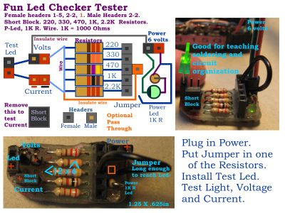


The Fun Led Checker Tester was something I needed for my workbench for a long time. Whenever you have an idea you start by going through your parts. Leds are in most of my projects. I have a ton of Leds, but most are junk. I bought a grab-bag of 500 Leds from Jameco.com that is worth every dime I paid for it. I have built about six projects with them. I was organizing my parts and I saw that my Leds were not junk. I just hadn’t checked them in years. To test a Led you have to get out the breadboard, a power supply, resistors and jumper wires. A mess. I had a little piece of plain prototyping board and I laid out the fun Led checker tester. I already had my battery box set up with a female header. I cut a piece of solid wire ribbon cable that I got at Radio Shack and I made a two conductor power cable for my Led tester. Done.
I sat in front of my computer watching a show on my AT&T U-verse and I tested and checked a drawer of my Leds. It was fun and easy and I know what Leds I have now. The best way to test most Leds is with 6 volts and a 470 resistor. That is the center resistor in my tester. As you can see you can check the voltage and the current of your Led to. My tester gives you how your Led will look hooked up in your circuit. No mess and you only need a DMM if you want to use one. The 1K resistor is what I use for 5 or 6 volts most of the time. That is half of the current of a 220 resistor. The 2.2K works up to about 12 volts. If you do test at 12 volts then change power Led resistor to 1.5K or 2.2K. My tester is a full functional test of your Leds with extras in a small cute format. Something I have needed for years. Build one.
My tester would be great for a soldering class and teaching circuit design and organization. For plain prototyping boards like mine you must hold the parts in with something like hot melt glue. Where possible I used the component leads to connect things. In these boards you must use a wire to connect almost everything or you will have big solder blobs all over your board. I made a few of them. The best wire to use is lead trimmings. The leads you trim off of the parts you install. I save mine in a compartment of my breadboard wiring organizer box.
The circuit is simple, but setup in a clever way. By using a jumper wire that is soldered into the board for the resistor header I saved some space and some work. You just stick the jumper into the resistor you want and the test is ready. No looking for a jumper wire or where to put one. Simple is more fun if you can get everything done with fewer steps. Organizing the circuit for ease of use makes the job more fun. I used enamel insulated magnet wire available at Radio Shack to run the Ground wire. I found space for one header by the jumper for a pass through for the test voltage. Cover the bottom of the circuit with hot glue or something to prevent shorts on your workbench.
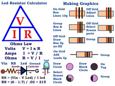
The Led Voltage is for the Resistor and the Power supply not the Led’s Forward Voltage. Use a modern Digital Multi Meter on the Diode setting to get the Led’s Forward Voltage. The Current is also affected by the Resistor and the Power Supply. A higher Resistor value means lower current for the Led. You can get a close resistor by using the Led’s Forward Voltage and the current from my Checker Tester. But, my Checker Tester gives you the Current and Voltage for your Led with the Resistor and the Power Supply that you are using. That is what you will use to find that perfect Led for your project.
In my breadboard wiring box I have Leds that I have installed a resistor in the positive lead. This makes them so easy to use in a breadboard that your ideas work much faster and will be more fun. This is the way I install a resistor into a Led. First about ½ inch down from the led you bend the positive lead out at about 90 degrees opposite of the other lead. Then about a ½ inch above the resistor you bend its lead out at about 90 degrees. You overlap the resistor lead about 1/4 inch passed the bend in the led lead. Solder the leads together between the bends. This method prevents too much heat from getting to the led. Trim off the excess lead ends and make the leads even. I put hot melt glue into the leads from the Led to the resistor. To test this type of Led put the ground in the led header. Touch the Jumper to the resistor lead of the Led. You could modify my tester to have a pass through for the test voltage. There is space where the Jumper is installed for one header.
Headers are cheap and easy to get today from sites like Jameco.com, Robotshop.com and DFrobots.com. I buy 30 to 40 contact headers. For the males you simply hold the right number of contacts with pliers and snap of the rest. They are called breakable headers sometimes. The female headers you must cut them apart even if they say they are breakable. You need a very sharp diagonal wire cutter for this. You cut on a contact not between the contacts. You lose one contact for each cut. The contacts make great little contacts for all sorts of things. You can use a Dremel sanding drum to clean up the cut sides of the female headers. I clean up the males sometimes. The headers come in colors now.
Headers are now in four basic types. Short lead or Printed Circuit Board(PCB) install. Long lead like the Arduino headers that fit into headers and male and female. I am using short lead standard Male and Female headers for this board.
Leds are fun and they can waste a lot of current. Brighter Leds use more current. As I said the difference in using a 1K instead of a 220 resistor is about half of the current of the 220. The brightness isn’t that different if you can use it. We like bright shiny things and in Leds that wastes current. On batteries that is a shorter play time. Trying your Led on 220 and then on the 1K makes my checker tester fun and functional. That is what gives you a perfect Led for your project.
My battery box has had the bus strip for a long time. It was in the processor explosion that I added the female header. For my projects I now use nice 1.5 amp 12 volt wall adapter and 9 volts, but with Leds and things I still use 6 volts. Having a battery box like mine gives you more things you can do. When adding to these battery holders be careful because the plastic melts at a very low temperature. Clean the contacts and use flux. I only put 6, 4.5, 3 & Ground on my header. It makes setting up a Led checker tester like mine very easy.
The four Led light board is a load for a dual power supply I am building. It makes a great light with dual control. I just put the resistors on top of my board, but you can put them anywhere. When you build a small circuit like this cover the bottom with hot melt glue so it doesn’t short out on your workbench.
Have fun.


