

Introduction: Getting Started With Chisel


Constructing Hardware in a Scala Embedded Language (Chisel) is a new way to describe hardware for Field Programmable Gate Arrays (FPGAs). This instructable will take you through how to set up a Chisel installation and a few cool things you can do with it. A familiarity with programming is assumed, but knowledge of FPGAs or verilog is not required.
What is an FPGA?
An FPGA is a chip that is designed to have its logic circuit hardware programmable (see here for comparison with similar devices). It is comprised of various little blocks called slices. These slices can be programmed to do various simple operations such as adding numbers or simple logic conditional statements. These slices are then connected together to perform more complicated tasks. One important difference to remember when programming an FPGA compared to traditional CPU programming is that, on a FPGA, all signals are being processed simultaneously, as opposed to sequentially and thus offers tasks to be processed at faster speeds for certain problems. This is where an FPGA has an advantage over other computing platforms.
What is Verilog?
Verilog is a hardware description language used to configure FPGAs. Chisel is a language used to generate verilog. After the design is completed in verilog it can be sythesised into the specific placement on the FPGA. This may generate a design as shown in the image from electronicdesign.com
Why Chisel?
One of the biggest issues with using an FPGA is that they are hard to program. Things happening simultaneously can be complicated. Chisel is a neat way to generate verilog with a very nice way to test your design. Additionally, it allows easy parametrization of hardware meaning your designs can be very flexible.
Step 1: Installation
First thing is to install Simple Built Tool for Scala-driven builds (sbt). There is already a good tutorial on how to install sbt at www.scala-sbt.org/release/tutorial/Setup.html, so no need to re-invent the wheel.
Next thing is to use git to clone the Chisel Tutorial Repo:
git clone https://github.com/ucb-bar/chisel-tutorial.git
Going into the chisel-tutorial/hello directory run:
make
This should download some files and make the example hello project. You should see [success] and PASSED. If you don't you may be missing a dependency which you need to find and install.
Congratulations! All installed! Now how to use it?
Step 2: Hardware Programming

This step is an introduction to hardware programming. If you already have done some verilog programming you may want to skip this step.
How are FPGAs programmed?
Programming an FPGA is different to other styles of programming. Rather than giving instructions to execute in order, you are describing the layout of the hardware. Describing it in a single block would be very messy and hard to read however. Instead, similar to functions in other languages the hardware is split up into modules. These modules are connected together to make more complicated designs. Each of these modules have input and output. By connecting these modules together similar to calling functions we can create complicated readable designs. The image shows an example of a module in chisel that adds two numbers. The top line imports Chisel. You will need to do this in all Chisel files. We then declare an adder module called myAdder. This added has two inputs x and y to compute the result z = x + y. UInt is short for 'unsigned integer' declared as an input or output with 16 bits. Notice how it is ":=" not "=". This is very important but will be explained later. The next step will demonstrate how to connect modules in Chisel.
Some basics Hardware Concepts
This section will describe a few of the concepts when designing in hardware.
The Clock
The clock is essential to understanding hardware design. It is a timer than synchronizes your design so that everything is running at the same speed. Hardware is generally split into two categories: combinational and sequential logic. Combinational logic such as a = b + c ignores the clock. Sequential logic uses the clock to determine when to read in new data into a memory element. A register or Reg in Chisel is an example of a sequential logic element. Each time the clock 'clocks' the value at the input of the register is remembered for later. In Chisel the clock is implied. This means you don't need to worry about connecting it.
Critical Path
The critical path in your design determines how fast the clock can run. Generally the faster the better. The critical path is the slowest combinational path between any two registers. Consider it in terms of a race between the clock and the slowest path. The clock has to be slow enough so that the data can race through the critical path to the register where it will be stored. Your design can be correct but slow if you don't think about it.
Step 3: Connecting Modules in Chisel


The Chisel tutorial which you downloaded before has some great example code with problems and solutions. If you would rather play with examples and modify them follow the section Completing the Tutorials in the README of the repo you downloaded.
The images above show one of the examples in the Chisel Repo. A multiplexor or mux for short is used to choose between two inputs. The first image shows a implementation of a multiplexor with two inputs, in0 and in1. They are both one bit in size. The sel bit then chooses between in0 and in1. If sel = 0 then out = in0, otherwise if sel = 1 then out = in1. After creating this module we can use it in another module to choose between 4 bits. To do this we now need two selection bits to choose which of the four inputs. Additionally writing in0, in1, in2, in3 is messy. So instead we use a Chisel Vec to say we want 4 inputs. This is similar to an array or list and we can access which bit that we want. We now create three Mux2 modules and connect them to our inputs and outputs. This finishes the 4 bit mux.
Operators in Chisel
Something you may have noticed is the mixing of the "=" and ":=" in the examples. They mean two different things. The "=" is scala. In the example above the modules are created as scala objects. The ":=" is used to connect 'wires'. This is the Chisel operator saying that the value of something should be connected to the output of something else. There are a few more such as in if statements where "==" is typically used to compare two scala objects where as "===" is used to compare the values of two 'wires' in Chisel. See chisel-tutorial.pdf for more details.
Step 4: Testing in Chisel

One of the strongest features of Chisel is how easy it is to do a thorough test of each module. Consider the Mux4 test in the image above. It loops over all possible inputs. The function poke changes the values at the inputs of the Mux4 module. Next is a step. This is only really needed for modules with registers but put in here anyway for a demonstration. It increments the clock in your design passing the inputs through registers. Finally there is the expect function is used to test. It expects the output of the Mux4 and output calculated in the test to be the same producing a "PASSED" or "FAIL" depending on the outcome.
The nice thing about testing in Chisel is that it can generate into C. This allows your test cases to be completed quickly. Compared to running and looking at the waveform, it is much faster and neater to debug if you write the test cases carefully.
I recommend attempting the example problems in Chisel now. If you are new to hardware design keep in mind that everything is simultaneous. You are describing a structure in Chisel rather than instructions to execute. Go to the next step after you feel you understand the basic structure of how to write something in Chisel.
Step 5: A Tale of Two Languages

Some verilog programmers might get to this step and say "Ok, the testing thing is nice and Chisel looks pretty but I can still do it in verilog. Why should I change?". The thing I like most about chisel is how easy it is to write stuff that is parametrized. To understand how powerful this is you need to realize that you are actually programming in two languages simultaneously, Scala and Chisel. The scala is run first creating the connections for Chisel. Chisel then uses this scala generated design.
Looking at the example, bitWidth and useReg are variables in scala. When scala executes, these variables are assigned values by modules higher up. This allows you to declare this module once and use it everywhere when you need a pipeline stage or not and for variable width adds. This example is trivial but consider its extension to an adder tree of arbitrary size with various configurations of pipelining to fully appreciate what it can do.
Step 6: The Power of Chisel
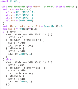
This step is just showing off some of the neat things you can do with Chisel. The image attached shows a state machine with a scala decision to choose between the "and" or the "or" operation.
This is just some of the things you can do to dynamically change your design at compile time. One very powerful concept for dataflow applications is optional registers. Passing in an array of booleans to switch registers in and out allows you to explore the design space easily to find a way to maximize the clock frequency.


