

Introduction: Getting Started With the Pmod HB5: Part 1


You've got your motors. You've got your microcontroller. Now all you need is a motor controller to connect the two!
But wait a minute! Simple motor controllers like the one in my Motor Controllers tutorial can only run a motor one way! What if you want to run a motor backwards or forwards!
In that case, you'll need an H-bridge!
If you've ready my Stepper Motor tutorial, you may have gotten the impression that I don't like H-bridges. That's not quite true. Because of how they're built, it's easy to short-circuit an H-bridge, which can damage the H-bridge, as well as your microcontroller, battery, or any other attached electronics*. This doesn't make them bad, you just need to be careful when using them!
In this tutorial, I'm going to show you how to use the Pmod HB5 safely, and prevent your code from ever short-circuiting!
Let's get started!
*Yes I have stories. Just ask.
~~~~~
For more things that I've done, you can check out my profile page!
For more info from Digilent or the Digilent Makerspace, check out the Digilent blog!
While you're there, consider signing up for the Digilent newsletter!
Step 1: What You'll Need

For this tutorial, I'm using:
- A couple of Digilent gear-motors (19:1 gear ratio, but they also come in 53:1).
- The Pmod HB5 (and 6-pin Pmod cable).
- A DP32 (with breadboard modification).
- A battery pack.
- Several wires.
Normally I would make the circuit directly on the DP32, but this time I'm using an HB5, because it pairs well with the Digilent gear-motors. Later on, in another tutorial, I'll show you how to use the encoder feedback from the Digilent gear-motors, that makes this pairing so attractive.
Step 2: Okay, But What's an H-Bridge?


If you went through my motor controller tutorial, you may remember that our microcontroller can use transistors to control much higher currents that it would be capable of on its own. An H-bridge does essentially the same thing, using the transistor as a gate to control the flow of current, but with a slightly more complex configuration.
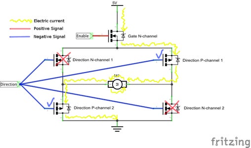
It's called an H-bridge, because the two pairs of direction controlling transistors form the legs of an H, while the motor forms a cross between them.
This circuit uses a mix of N-channel and P-channel transistors. To find out more about the difference between these, check out brmarcum's tutorial on MOSFET transistors! For now, all you need to know is that an N-channel MOSFET will "open" and allow current to flow through when a positive signal is applied to it. A P-channel MOSFET does the opposite, closing with a positive signal, and opening with a negative signal.
As you can see above, when a positive signal is applied to our direction transistors, the N-channel ones open, the P-channel ones close, and current is allowed to flow through the motor in a positive direction! When a negative signal is applied, the transistors all switch, and the current flowing through the motor reverses!
Step 3: Cool! So What's the Catch?


Well, as much as we'd like to pretend that transistors and microcontrollers are purely digital (either on or off), in the real world, they can function at a whole range of voltages. The picture above is a capture of the actual signal, output from a so-called "digital" signal, and you can see that it bounces several times before settling.
I've talked about bounce severaltimesbefore, but usually that's with regards to signal processing and filtering. In this case, bounce can actually destroy your transistors!
If we switch direction, without first using the Enable transistor to cut power to the circuit, that bounce could allow both our N-channel and P-channel transistors to stay open at the same time. This causes a short directly from power to ground! Because electricity wants to flow through the path of least resistance, it'll bypass our motor entirely, and jump straight to ground with extremely high current! This current can be high enough to make your transistors catch fire and literally glow like an LED*.
THAT is what I'll be showing you how to prevent in your code!
*I did mention I have stories, right? I have stories.
Step 4: The Pmod Cable

The wiring for this project is extremely simple. There are six pins on the HB5, and we'll only really use four of them (for now).
Before we start wiring things, look closely at the Pmod cable in the first picture above. Notice the little paw-mark on one corner of both ends of the cable? That mark is there to help you keep track of which pin is which. The pin closest to the paw-mark on one end of the cable, is connected to the pin closest to the paw-mark on the other side. The second closest is connected to the second closest, and the rest follow suit.
That way, when I plug my HB5 into the Pmod cable, I know if I put the paw-mark next to the 1 pin, the corresponding pin on the other side will also be closest to the paw-mark. Make sense?
Step 5: Wiring the HB5

With that out of the way, we can get on with wiring. Remember to pay attention to the paw mark! It doesn't show up in the picture above because the cable is turned around, so I took the liberty of drawing it in.
The pins on the HB5 are:
1 DIR, our H-bridge direction pin.
2 EN, our H-bridge enable pin.
3 SA, signal A of the motor encoder (you can ignore this for this project).
4 SB, signal B (ignore this as well).
5 GND
6 VCC
As you can see above, I've attached GND and VCC to their compatriots on the DP32. DIR got connected to pin 7 (RB14), and EN got connected to pin 6, which is also a PWM enabled pin.
It's important to connect EN to a PWM pin, because that will let us use PWM to control the speed of our motor!
Step 6: Connecting the Motor and Batteries


As you can see, I've also connected the motor and batteries to the HB5.
IT IS VERY IMPORTANT that you don't connect your batteries backward! This will cause your HB5 to get very hot! It won't kill it, but it certainly isn't good for it.
Personally, I made a point of leaving the batteries disconnected until I was ready to run the motor.
Step 7: The Code and What It Does


Now you're ready to download the code!
Before you upload and run it, I want to give a quick overview of what the code actually does.
The loop() function works similarly to the sweep function for servos. It has a variable (in this case, i) which it sweeps up to 255, and then back down. The big difference here is that we don't stop at zero! Our variable goes all the way to -255! Those negative numbers will make our motor spin backwards!
Instead of using the analogWrite() function directly, we call the setSpd() function (the second picture of this step). This will interpret our -255 to 255 speed value and send directions to our DIR and EN pins accordingly.
The really important feature of this function is that it keeps track of which direction our motor is currently spinning! If we're spinning forward (values 1 to 255), and we want to switch to reverse (values -1 to -255), it will call the changeDir() function.
The changeDir() function is what safeguards us from shorting out our H-bridge, and I'll explain it next.
Attachments

Step 8: The ChangeDir() Function

This function is what keeps us safe. If you recall, it was changing the direction signal of our H-bridge that could cause us to short out.
Whenever we want to change direction, the changeDir() function first sets the EN signal to zero. That closes the enable transistor of the H-bridge, cutting power to the rest of the circuit. With no power to the circuit, we can change our direction without trouble! But, if you recall, signals don't switch instantly, so immediately after setting EN to zero, we wait for 5 milliseconds.
After everything's nicely settled, then we can switch our DIR signal, but of course we need to wait again for everything to settle. After that, we can reset our EN signal to whatever it was before, which turns our motor back on.
Step 9: A Note on Settling Times

A millisecond might not seem long to you, but to electrical circuits, it's an eternity! In fact, if you check our graph of signal bounce, you may notice that it's pretty much settled after 250 nano-seconds. That's 1/4000ths of a millisecond, which means 5 milliseconds is 20,000 times longer than we need to wait!
You can probably stand to wait a little less time than 5 milliseconds, but personally I didn't see any reason to.
Step 10: A Note on Using This Code


This is some pretty slick code if I do say so myself! At the very beginning of the sketch, I've included several constants that allow you to customize its behavior a little.
The first constant I defined is a debugging flag that will not only activate the serial communication, it will slow the motor down so you can see how each change in speed or direction works. To activate debugging, you just need to change that variable to "true", and it will activate lines of code in all the functions that tell you what's going on.
The next two constants are the pins I had connected my DIR and EN signals to. If you're using a board other than the DP32, or if you just want to change which pins are connected to what, you can change these constants to match, and the code will change to match!
Finally, I included a really useful INVERT constant. Generally, when working with motors, you'll assign an arbitrary "forward" rotation direction. It would be nice if, when you gave those motors a "forward" signal (like our positive speed values) the motor actually ran forward.
Unfortunately that's not always the case, but with the INVERT constant, you can fix that! If you switch the INVERT constant, the direction the motor spins when you give it a positive value will reverse. That way, if the motor direction isn't the way you want it to be, you can change the INVERT constant, re-upload the code, and now it will be!
Neat right?
Step 11: Debugging


Previously, I mentioned the debugging constant, and how it could turn on or off the debugging messages. The way this works uses #if statements throughout the code (you can see one in the first picture above).
These are different from normal if statements, because they're not actually run by the microcontroller, but by the compiler itself!
When the compiler sees a #if statement, it evaluates it to see if it's true or false. If it's true, it includes everything inside the if statement in the compiled code. If it's false, it ignores all that code. That means that if you don't want to deal with debugging messages, then the compiler doesn't even give that code to the microcontroller!
It's a neat little way of automatically cutting out any unnecessary code from the final product, making it smaller and more efficient!
Step 12: That's It!

This tutorial is meant as a sort of theoretical introduction to H-bridges, and how to use the Pmod HB5. It's not the most efficient method of handling H-bridges, but it does a good job of helping you understand what pitfalls to avoid, and how to avoid them.
The big issue with this method are those delay() functions in the changeDir() function. Those are generally bad, because your microcontroller is forced to halt everything until they're done waiting. In part 2, I'll show you how to use something called a "state machine" to avoid those delay() functions, without risking a short in your H-bridges.
As usual, this is just the start of a much bigger project for me. You may have noticed that we ignored the SA and SB pins on the HB5. Those are connected to the hall-effect shaft-encoder that's built into the Digilent gear-motors. Soon, I hope to show you how to tap into those, and how to set up a high-quality PID that will let you get very precise control out of your motors!
I hope this tutorial was useful to you, and I can't wait to take it further from here!


