

Introduction: Getting Started With the ESP8266 ESP-12


This instructable will cover the basic steps that you need to follow to get started with the ESP8266 ESP-12.
A lot of this content is already out there, but I had a hard time getting everything in place, and the different tutorials can cause a great deal of confusion, which is why I have tried to make the simplest setup possible.
Specifically, this instructable will cover how to make the ESP-12 behave as a WiFi client by connecting to your home wireless network and how to send sensor data ( we will send random numbers to test, and will not really be covering sensors in this instructable) to a Thingspeak channel.
The following are the materials we will be using :
2. CP2102 USB to UART Serial module
3. LM1117 3.3V Voltage Regulator
4. Jumper Wires
5. 5V Power adapter
Step 1: Breakout the ESP8266 ESP-12 Onto a Perforated Board

The ESP-12 has a 2mm pitch, which means you cannot access all the pins on a breadboard or a perforated / dot matrix directly, which have a 2.54mm pitch (distance between adjacent pins).
You could use a Xbee adapter board, but there's an easier way out. Take a small length of single strand cable or multi strand cable, and get a spider web breakout like this. I added two rows of pinouts, to make sure the pins were handy. Here's what it looks like.
Step 2: Add Power Supply
Add a power barrel so that you can easily plug in a 5V adapter into your board to power it. This is an optional step, but one that saves you a lot of trouble later.
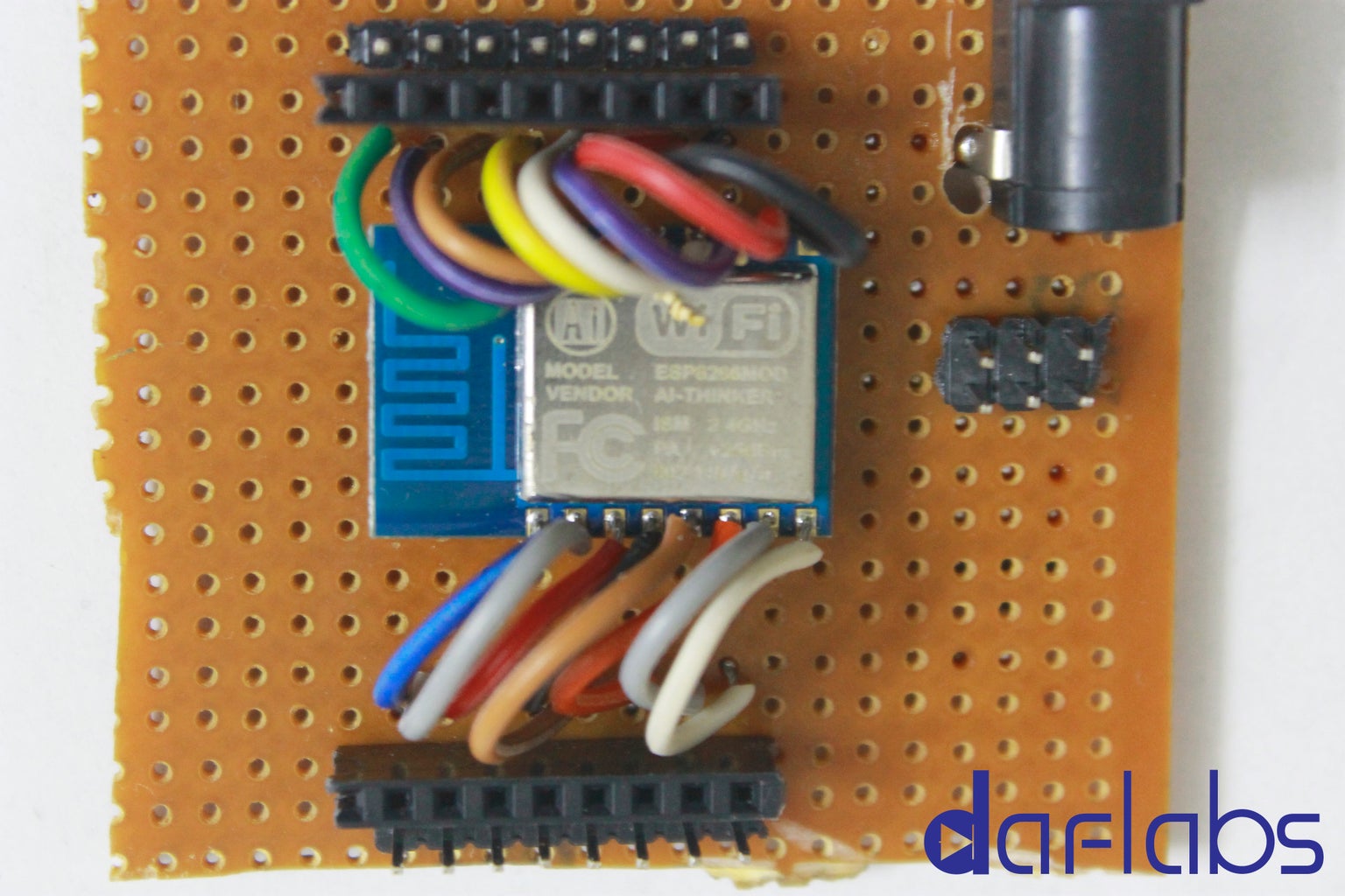
Connect the terminals of the power connector to the LM1117 (SMD), so that you have 3.3V output to supply to the ESP8266 ESP-12. It is good practice to add capacitors across the input and output lines, but I am just going to skip that, since this application is very basic and is non-essential.
Here is what the board looks like after adding the power connector and the LM1117.
The additional jumper wires are so that I can either channel the power from the connector to the LM1117 (if I am using a power source > 3.3V), or directly to the ESP-12 (if I am using a 3V power source). This is optional, and you do not need to add this.
Step 3: Make the Connections

You need to connect a few GPIO pins on the ESP-12 to 3.3V or Ground, to set it in the right mode for communicating with it. Here are the connections you need to make :
VCC ----> 3.3V Power supply (Vout of LM1117)
GND ----> Ground of power supply
CH_PD ----> HIGH (3.3V)
GPIO2 ----> HIGH (3.3V)
GPIO15 ----> LOW (GND)
GPIO0 ----> HIGH or Floating for AT Mode (3.3V) [ * if you want to flash completely different firmware then you must connect it to ground ]
Step 4: Plug in Your CP2102

You will now need to plug in your CP2102 to the USB of the computer.
The CP2102 is a USB to serial converter that lets us communicate with the ESP-12 over UART.
The CP2102 will be detected as a serial device. If you have used a serial device before, you ideally should not need the drivers. In case you need the drivers, you can find them here : CP2102 Serial VCP (Virtual Communications Port) Drivers
The connections between the CP2102 and ESP-12 are straight-forward.
CP2102 <--------> ESP-12
Rx <----------------> Tx
Tx <----------------> Rx
GND <----------------> GND
Note : Do NOT connect the 3V3 line from the CP2102 to the ESP-12. The ESP-12 consumes a lot of current, and the USB port is NOT capable of providing that, you are at risk of blowing the USB port if you connect the two.
Alternatively, you can also connect an Arduino Uno 's Rx and Tx lines with the CP2102, but you will need to have a voltage divider resistor arrangement to step down the 5V UART lines from the Uno to the 3.3V needed by the ESP-12, otherwise you risk damaging the ESP-12.
Step 5: Open a Serial Terminal
Depending on your OS, you can download and install a Serial Terminal to communicate with the ESP-12.
Here are some popular ones :
Linux / Windows: Putty Download
Mac: Coolterm Download
If you have Arduino IDE installed, you can just use the Serial Monitor present inside. For that, you have to navigate to Tools > Ports , select the Port that the CP2102 was detected on, and then open the Serial Monitor.
For the next few steps, we will be using the Arduino Serial Monitor for demonstrating.
In the Arduino Serial Monitor, at the bottom right, in the line endings tab, select "Both NL and CR". This inserts a NewLine and CarriageReturn at the end of each command you send, and is necessary for the ESP-12 module to receive and understand your commands.
The other terminals should have a similar option in their respective configuration pages.
Step 6: Setup the Communication Parameters

First, to check if the module has been recognised and is accepting commands, just briefly connect the "REST" pin of the ESP-12 to ground, using a jumper. This resets the ESP-12 and you should see something like the screenshot if this works well.
Next, we run the following set of commands in the Serial Terminal:
1. AT
This is just a hello message, and if the ESP-12 is in the correct mode, it will return an "OK" message.
2. AT+GMR
This command returns the firmware version currently on the chip.
3. AT+CWMODE?
This command returns the mode of operation. If the mode is not 3, we will change it to 3 using the following command :
AT+CWMODE=3
This mode makes the ESP8266 behave both as a WiFi client as well as a WiFi Access point.
4. AT+CWLAP
The LAP (List Access Points) lists the WiFi networks around. Next, we choose our WiFi network
5. AT+CWJAP="your_network_name","your_wifi_network_password"
This command JAP (Join Access Point) makes the ESP-12 join your WiFi Network.
6. AT+CIFSR
This command returns the IP address of the ESP-12 as the second line and the gateway IP address as the first line if it managed to connect successfully.
Step 7: Post Your Data

Next, we just post our data to Thingspeak. For now, we will be posting made up numbers, which you can replace with sensor data if you are using an Arduino Uno or some other micro-controller with the ESP-12, or once you progress to using the ESP-12 with your own custom firmware.
You need to sign up for an account at Thingspeak, set up a channel, but to make the process simpler, I am just going to include my access key for Thingspeak, so you can send data right away to test your modules and view it too.
You can view the data you posted here :
Commands :
AT+CIPSTART="TCP","api.thingspeak.com",80
The above line opens a connection with api.thingspeak.com on Port 80, to send an HTTP GET request with our data
AT+CIPSEND=70
The above line specifies the number of bytes that are going to be sent as a part of the request. The length is the length of the line below, plus 4 bytes for the CR,NL (Carriage Return and New Line) that the Serial Terminal always inserts at the end of a command. If the size is not correct, you will get an error.
Once you enter that, you will see the " > " symbol in the window, which means you are now ready to send the actual data. Enter the line below, with the numbers you desire, and press Enter. Then press Enter one more time.
GET /update?api_key=QNI517W61UOC40KF&field1=12&field2=19&field3=94
The above three commands effectively call the URL http://api.thingspeak.com/update?api_key=QNI517W61UOC40KF&field1=12&field2=19&field3=94
The api_key is necessary for authentication, and field1, field2, field3 are the data fields for our example.
You can now go and view the data you just posted at the link here : Sensor data on Daflabs Test Channel on Thingspeak
Step 8: And Done !
Congratulations, you are now done ! You have just posted some data to the web using the ESP-12 and GET requests.
You could extend this by adding some sensors to an Arduino Uno and interfacing it with the ESP-12, and automate the entire process of sensing and updating data. What you effectively have here is an Arduino Yun (minus the Linux) for a mere $5 more !
For a tutorial on how to use the Arduino with the ESP-12 and the code for uploading sensor data, you can visit here: An IoT project with ESP8266 and Arduino


