

Introduction: Getting Started With the Interaction Parts Kit Part 1


In this tutorial I will show how to use a potentiometer to control the brightness of an LED. Also, I have a tilt switch (described later) in series with the LED so that when the breadboard is upright it will light up, but when the breadboard is flipped sideways or upside-down it will turn the LED off.
This tutorial assumes that you have LabVIEW installed and you also have LabVIEW MakerHub LINX installed. Check out this Instructable to see how to get started with LabVIEW MakerHub LINX. If you have LabVIEW Home Bundle, check out this Instructable with in-depth instructions on how to install it on your computer.
All parts from this project are found in the LabVIEW Interaction Parts Kit by Digilent. Also, if you want to purchase LabVIEW Home Bundle and a chipKIT WF32, check out the LabVIEW Physical Computing Kit!
Step 1: Materials


1. chipKIT WF32 or other board that supported by LINX. Here is a list of supported LINX devices.
2. LabVIEW MakerHub LINX
3. LabVIEW
4. 10k Potentiometer
5. Tilt Switch
6. LED
7. Mini Breadboard
8. USB A to Mini B cord
All parts are found in the LabVIEW Interaction Parts Kit
Step 2: Setting Up the Potentiometer

First, we want to connect the potentiometer to our board so that we can start getting values from it. Check out this article to find out more about what a potentiometer is.
First, we want to supply 3.3V to one end of the potentiometer and connect the other side to ground. The wiper (in the middle of our potentiometer) voltage can then be measured by connecting the wiper pin to the Analog Input 0 pin on our microcontroller. Check out the picture above to make sure your potentiometer is set up correctly. Now let's create a LabVIEW VI to read our analog signal.
Step 3: LabVIEW VI

Open up LabVIEW and create a new VI. Open your functions palette and go to MakerHub -> LINX and drop the LINX Open and LINX Close VIs on the block diagram. Since we are reading an analog signal, we'll need to also go to LINX -> Peripherals -> Analog -> Read.
Now that we have those blocks on our block diagram, we want to connect them all up and create a while loop so that we can read our analog signal until we click a stop button on the front panel. First, open the functions palette and go to structures -> While loop. Create a box around our analog read block. Right click on the tiny stop sign in the bottom right side of our while loop and create a control. This will allow us to stop the while loop from the front panel so our code can finish when we're done with it.
Next, create a control on the LINX Open block for our serial port and create a control for the analog channel on the analog read block. Connect the resource and error wires from the LINX Open VI to the Analog Read VI. Now connect the resource and error wires from the Analog Read VI to the LINX Close block. Now create an indicator on the analog read block for the voltage by right clicking on the voltage terminal on the block and clicking "create Indicator". When you're done, your front panel and block diagram should look like what I have pictured above.
On the front panel, select your com port from the Serial Port control drop down menu. Then make sure that the Analog Channel control is set to 0 since that is the channel our wiper voltage is connected to. Click run and you should see your voltage reading in the indicator on the front panel.
Step 4: Wire Up the Tilt Switch and the LED

If you're not sure what Pulse Wave Modulation is, check out this Wikipedia article for a general description of what it is and also read over this learn module from Digilent that goes over how to use PWM to control the brightness of an LED.
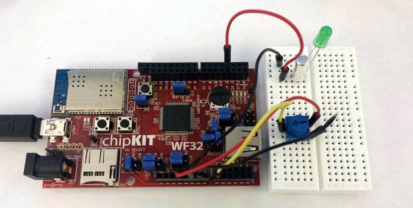
Now we'll wire up our tilt switch and LED. First, we'll want to connect a Pulse Wave Modulation (PWM) channel from the chipKIT WF32 to the tilt switch by connecting channel 3 to our tilt switch. Channel 3 is one of the dedicated PWM channels on the chipKIT WF32. All PWM channels on the chipKIT WF32 are underlined on the silk screen. A more reliable way to find the PWM channels is to read the reference manual for your board.
Next connect the other lead from the tilt switch to the anode of the LED. Then connect the cathode of the LED to ground. We want to connect the PWM line because you can use PWM to control the brightness of the LED. Higher duty cycles result in a brighter LED.
When the tilt switch is sitting flat, it allows current to pass through but when the tilt switch is sideways or upside-down, it will stop the current from reaching the LED.
Check the picture above to make sure you have the correct setup.
Now that we have our wiring done, we can write our LabVIEW VI to control the brightness of our LED using our potentiometer.
Step 5: Final LabVIEW Code

You can find the PWM block in LabVIEW under MakerHub -> LINX -> Peripherals -> PWM -> Set Duty Cycle. The PWM block requires a PWM channel control and a PWM value ranging from 0 to 1 where 0 is 0% duty cycle and 1 is 100% duty cycle. We want to have a PWM of 0 when our analog reading is 0V and we want to have a PWM of 1 when our analog reading is 3.3V. Thus we need to take the reading from our Analog Read block and divide it by 3.3.
An important note is that the block can only take ranges from 0 to 1. Thus we need to use the "In Range and Coerce" block in LabVIEW to limit our results to the range 0 to 1. To do that, feed in the result from dividing by 3.3 into the "x" port of the block. Then create a constant 1 for the upper limit and a constant 0 for the lower limit. The coerced x output from the block is what we want to send to our PWM block so go ahead and connect them together.
Now create a control for the PWM channel.
We'll also want another set duty cycle block considering that if our duty cycle is nonzero, our LED will remain on after you press the stop button and the VI ends. Put the other block outside of the while loop but before the LINX Close block. Connect up the same PWM Channel and create a constant 0 for the duty cycle and delete the resource and error wires from the while loop and the LINX Close. Then connect the resources and error wires to the added duty cycle block and then connect them from this block to the LINX Close.
We're done! Check your block diagram against the one pictured above. On the front panel, make sure the Serial Port and Analog Channels are the same as before and set the PWM Channel to 3.
Click run and observe that as you turn the potentiometer, the LED brightness also changes. Also, if you tilt your breadboard upside-down, the LED will turn off. Below is the VI for this demo.


