

Introduction: Google Play Music Internet Radio (Raspberry Pi and Arduino)


All code and CAD drawings can be found in the GitHub repo.
Before we begin I should probably point out that a reasonably good understanding of electronics and Linux makes this project a lot easier, especially since my Instructables are probably not the easiest to follow (I do try my best), however feel free to ask if something isn't clear enough.
A full parts list is a little difficult for a project this size so I'll highlight the important parts only:
- Arduino IC (i.e. ATmega 328 with Arduino bootloader, you can but them blank and flash then yourself or pre flashed with a bootloader)
- Raspberry Pi (512MB version if possible, because you know, more memory is better... but seriously I haven't tested with a 256MB version, but it should still work)
- Digital potentiometers (logarithmic taper (we'll be using it to attenuate audio) & i2c (from the Pi), a DS1807 will do)
- Amplifiers (I used pre-built modules but feel free to build your own if you feel up to it)
- DC-DC converters (12v to 5v, 600mA output, isolated)
- Rotary encoders (from font panel, cursor movement and volume)
- An LCD (4 rows, 20 columns works for me, if you have songs with really long names maybe get a 40 column one)
- Bus Pirate (I don't actually have one, but they are very useful, alternatively you can do what I do and write Arduino scripts to make an Arduino act like a Pus Pirate to some degree)
- Laser cutter/engraver (not essential, but makes production of mounting hardware and front panels SO much easier)
- Router (for construction of enclosure)
- Accurate callipers (essential for measuring sizes for panels and mounting hardware)
Video demoing the finished radio:
I'm having problems embedding videos in my Instructables, here is a link to YouTube: http://www.youtube.com/watch?v=tgPbvo-8iRc
Step 1: User Interface Electronics


In that case first up is the electronics which control communication between the radio and the user, in my radio the included 6 buttons, two rotary encoders which also have a switch for when they are pressed and a 4 row, 20 column backlit LCD, the majority of this is controlled using a ATmega 328p which interfaces with the Raspberry Pi using RS232 (over a level converter, since the Pi has a logic level of 3.3v and the Arduino is 5v), the one exception is the LCD backlight which is switched on and off using a GPIO pin from the Pi.
So here is an overview of what IO devices were actually connected to the Arduino, how they were connected and why:
- Pins 0 and 1 connected to the Raspberry Pi GPO header through a MOSFET level converter, this was for the serial communication between the Pi and the Arduino.
- The front panel button were connected to ADC pins 0 to 5 with either an external pull up or pull down resistor (whichever is easiest, in hindsight pull up would have been easier then I would only need ground on my front panel board).
- The LCD is connected on digital pins 8 to 13, the actual pin assignment is not important at this stage as it can be configured in the Arduino script.
- The encoder buttons are on pins 6 and 7, using the internal pull up resistor.
- The encoders are on pins 3 and 5 and 2 and 4, it is important to have at least one interrupt pin per encoder, this will greatly improve the performance.
Step 2: Front Panel and LCD


Before starting this step it is a good idea to know roughly what size you want your radio to be, as this will limit the maximum size of your front button/encoder panel.
Once you know roughly what size you need to make your front panel you can design it however you like to match the style of enclosure you are planning, the only constraints are that the use the same Arduino code as me (at least without vast changes) it will need to use the same type and function of inputs.
My front panel was simply built on stripboard and bolted to an Acrylic panel which would later be mounted in the enclosure.
On the LCD module I soldered on a small breakout board which tool the 6 and 4 pin ribbon cables which came from the main board and connected them to the appropriate pins on the LCDs 16 pin header.
a 5v and ground wire was needed between the LCD breakout board and button/encoder board as the encoders needed a ground reference and the buttons needed a 5v reference in order to work properly.
Step 3: Arduino Script
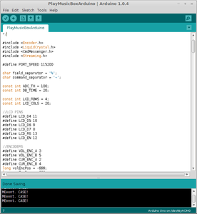
- You are using pull down resistors on the ADC
Starting on line 174 you will see a lot of tests that look like this: analogRead(PLAY_ADC) <= ADC_TH
Change this to >= and you should be fine. - Pin configuration
You will almost certainly have to change some pin assignments, this is done from lines 26 to 60, all the pins are well labelled in the script.
Once you have made all your changes, upload the script to the Arduino either by using an Arduino board to upload it or connecting a serial connection to the IC in circuit (I just used a Uno board, it is easier).
Here may be a good time to build the circuit so far on breadboard and test to ensure that everything is working as expected and you get the correct serial data when input devices are actuated and that the LCD responds correctly to serial commands. It is not essential that you do this here, if you prefer you can test the entire circuit before it is moved to the PCB.
Step 4: Audio Electronics


A summary of the audio signal path is as follows:
- Raspberry Pi output, close to an unattenuated signal, I used alsamixer to set the output to 0dB.
- Line out header, if used this would be a 5 pin 3.5mm jack which breaks the signal path if a plug is present in the socket.
- Digital potentiometers, these are used to attenuate the audio signal prior to amplification, controlled and powered by the Raspberry Pi over i2c.
- Headphone output, outputs attenuated audio output for use with headphones.
- Attenuation potentiometers, I added a footprint on the board for this but just bypassed it as it was not really needed.
- Amplifiers, 2 12W amplifier modules.
- Speakers, make noise :)
My audio electronics are probably not the best designed, and I certainly did not use the best quality speakers (mainly due to size restrictions to fit them in the enclose I had designed) so feel free to improve this in any way you can.
Step 5: Other Electronics

- Amplifier and LCD Backlight power switching
This was done from two GPIO pins on the Raspberry Pi (since I had maxed out the Arduino), all this involved was a MOSFET level converter switching an PNP transistor.
In the case of the LCD backlight, this directly powered the LCD backlight LEDs through a potentiometer which could be used to set the brightness.
To control the amplifier power a relay was used which was switched by the PNP transistor (with a protection diode). - Power conversion
I was powering the radio with a single supply 12V PSU which could deliver 1.5A constant, this supplied enough power however I had to convert it to 5V for both the ATmega IC and Raspberry Pi, to do this I used two switchmode DC-DC isolated converters, one for the 5V power plane on the main board and one to power the Raspberry Pi.
I used isolated converters as this removed a ground loop which caused problem with the audio circuit. - Power supply
I added an additional board (not depicted on schematic) which included a 1000uF capacitor which helps to compensate for the rapid change in power demand when the amplifiers are powered up.
This board also has a 20mm cartridge fuse holder fitted with a 1A fuse for the sake of protection.
Step 6: Main PCB

I had several problem when I was getting my PCBs produced (I did intend to have one for the front panel as well), as a result the current schematic in KiCAD has been altered to reflect some basic mistakes I made when designing the original circuit, therefore my original PCB design is no longer included in the KiCAD folder, however you should be able to export a new netlist and layout your own PCB if you wanted to have one made.
I did manage to use the PCB that was produced but it needed a bit of work to correct some errors that were made, some by me and some by KiCAD, but I should have noticed all of them regardless (moral of the story: always check gerber files before submitting them).
Therefore I will not go into too much detail about this, since my board will certainly be different to yours.
Step 7: Pi Setup and Python Script

- First set up the Pi to suit your network, etc., setup SSH if you want (it is quite useful but not essential) and ensure the Pi boots to a desktop environment.
- Install required libraries for GStreamer.
This can be done by running the following commands:
"sudo apt-get update"
"sudo apt-get upgrade"
"sudo apt-get install libglib2.0-dev gstreamer0.10-alsa gstreamer0.10-tools libgstreamer0.10-dev libupnp-dev libxml2-dev gstreamer0.10-ffmpeg gstreamer0.10-plugins-base gstreamer0.10-plugins-good gstreamer0.10-fluendo-mp3 gstreamer0.10-pulseaudio pulseaudio" - Install other libraries
Following the setup instructions available on the project pages is probably best (if nothing else they will certainly be clearer than my instructions ;). - Move your Python script to the default users home directory (most likely /home/pi/)
- Configure autostart
I did this using a basic autostart entry in /home/pi/.config/autostart/, my entry was as follows:
gpr.desktop
[Desktop Entry]
Encoding=UTF-8
Type=Application
Name=GooglePlayMuscClient
Exec=lxterminal -e "python /home/pi/GooglePlayMusicClient.py"
Step 8: Initial Test


If you have any big problems then you will know my now, most of the problem I had were with a bad software setup in which case the Python script will never get this far, so any problems from now on (in my case at least) are more likely to be electronics problems.
If all is well so far you will soon see the home screen of the radio on the LCD, you can now use the cursor rotary encoder to scroll through your library and playlists, the next thing to do is try playing a song, there will be a small delay between pressing the encoder and the song start to play (this is to allow time for the amplifiers to power up) but the LCD should now say the name of the song, artist and album.
This is the other point at which I had most of my problems, after a lot of head scratching I found that the Ethernet controller IC on the Pi was losing power for a short time when the amplifiers powered up, this was because of a small error in my circuit design which has been fixed in the current schematic, however if you have a similar problem it is most likely a power supply issue, to be sure watch the status lights on the Pi, the 100M light going out for a second was what gave the problem away for me.
If all is good here then you can go on to test other functionality (such as Last.fm, amplifier power, further menu browsing) until you are satisfied that everything works, once you are it's time to start thinking about making a nice case to hide all of that ugly electronics (in my case anyway).
Here is a video of a really early test (back when this project was a mess of components on my desk at Uni):
Step 9: Enclosure Design and Construction


Again as with the electronics I won't be going in to a huge detail about how I made my enclosure, however if any part is unclear then let me know and I'll do my best to improve it.
From the start I had decided that I would have a 1930s/1940s style enclosure for this project, no other reason other than I like the design of them, and I suppose there is a certain appeal to mixing new and old styles.
I have to admit that I got quite a lot of help with the construction of the enclosure from my dad so I don't have a great deal of photos of it's construction, however I shall do my best to describe the process used to make it.
The arched section was made in two halves that join at the top, each half is 3 layers of 6mm flexible plywood laminated using a layer of PVA wood glue between each layer. Each of the halves was clamped in a jig to get the correct shape while the glue set.
The front and rear panels were cut from 6mm birch plywood and had the various holes cut (for the speakers, LCD, panels, etc.) using a CNC router, the holes for the mounting hardware were drilled as required.
The base is a two layers of 18mm plywood, one of which is the molded bottom layer and the second forms the step on whih the top section of the enclosure sites and is screwed into. The edge of the bottom later was molded using a hand router.
The front and back plywood as well as the bottom section of the enclosure were all sprayed with a clear lacquer which both protected the surface of the plywood and improved the colour of the birch. The arched section of the radio was sprayed matt black which gives a unique style to the radio and makes a nice effect using the grain of the plywood. (look familiar?)
Finally an aluminium mesh was applied to the rear of the speaker holes to hide the speakers and internal components, this was simple cut to match the contour of the arch and held in place using Araldite. In retrospect this was only partially successful, you could still see the speaker mounting bracket through the mesh.
Step 10: Mounting Hardware

Designing how each section of the electronics would be mounted in the enclosure was a little difficult with limited space and places where things could be mounted, partially due to limited space and limited cable length between components, but the end result did not turn out too badly (I just hope I never have to replace the fuse...).
All of the mounts mentioned here were laser cut, you can find the LibreCAD files in the GitHub repo.
The first (and easiest) item to mount was the two amplifier modules, these used an acrylic mounting plate to screw onto the sides of the enclosure (which are around 18mm thick so can have a small self tapping screw go into them with no problems) and could be mounted almost anywhere as I had relatively long ribbon cables to connect them to the main board.
Next in was the speaker mounting bracket (complete with speakers), this was a little tricky to get in as there was very little space to get in with a pair of pliers to tighten the nuts properly on the screws protruding from the front panel, since this section will be vibrated by the speaker during use it is a good idea to use nylon lock nuts or two locking nuts to prevent them from vibrating loose over time.
Next up was the front panel board mounted on an acrylic panel with the correct cut outs for the buttons and encoders, this acrylic panel would both to the inside of the enclosure, resulting in the controls being recessed into the front of the radio slightly (I explain this terribly, see the photo), the top edge of the acrylic panel also acts as a spacer for the LCD module...
Which is next to be mounted, this is mounted directly into a cut out just the right size for the actual module (the black part, not the PCB) the PCB is then spaced back from the plywood using the button panel acrylic on the bottom and a small acrylic spacer at the top, the PCB is then held in with four retention clips which are bolted to the front plywood (this is maybe a little bad practice, but it works).
Now I need to fit in the main PCB somewhere, to do this I used an acrylic bracket to mount it to the side of the enclosure (originally planed to mount it on the base of the enclosure, but several ribbon cables would not reach it there), I was now able to connect the cables between the main board and the front components, amplifiers and speakers.
The next parts start to get a little tricky as it involves trying to connect cables to the Pi whilst holding to top section of the enclosure, next I mounted the Pi on the base of the enclosure which lined up with the cut out on the rear plywood, having done this I then had to connect the USB power connector, audio output and GPIO cable.
Finally, I mounted the power board to the base of the enclosure under the main board bracket (making fuse replacement a pain, but there was no other good place for it) and connected the rear power panel (which is held into the rear plywood with Araldite), the top and base sections of the enclosure could now be joined, making sure not to damage the questionably positioned USB header on the Pi, and finally connect power in from the power board to the main board.
Step 11: Final Assembly and Test


I finished off the enclosure with some black Japanned screws on the side of the enclosure to hold the two sections together (they went well with the black paint), some nice polished aluminium knobs for the rotary encoders and a back panel to cover the access door (to do this I had to glue a section of MDF on the inside of the enclosure to stop the cover from falling in) which was held in using some acrylic brackets screwed onto the back of the radio.
You may also notice I did not label the front panel controls, I did plan to laser engrave the button caps and knobs (originally planned to be hardwood), then the plan changed to laser engraving the panel, but from past experience it looks so much better now than it would if I had done this. Furthermore a lot of the controls are very intuitive; next track button is right of play, pressing the cursor encoder selects, back is the closest button to cursor encoder, pressing volume encoder mutes, red button is for Last.fm love, etc.
And now if you connect an Ethernet cable and 12V power then turn the power switch on you should still be greeted by the "Waiting for Pi..." message and in a minute or so should see your music library.
Find a good song and enjoy it, that's what I did next.
But back to testing, I played quite a varied selection of music to get an idea of what the sound quality is like and was quite surprised how good it is for most songs, if anything mid frequencies are a bit weak and bass is a bit strong (surprising given the type of speakers I use). I also found that above volume 40 you can hear a little hiss when playing a quiet song, which I can live with, it is not anything as loud as the music is at this volume it's just when there is a song with large changes in volume that you notice it during a quiet part.
As for software performance, every thing works, it could certainly work better though. There are a few optimisations I can think of which would make the radio a lot faster, mainly during boot (keeping on offline cache of the library dictionaries is what I'm thinking), but this will do for now, even on my slow connection now I am listen to my radio, writing this Instructable, downloading photos to add to and hosting a Minecraft server, so the main problem is mainly the long boot time.
Step 12: Review and Future Improvements


Some things that I could work on to make this even better:
- The local caching I talked about in the last step
- Improving audio quality
This would be done with better designed audio electronics and by fixing the PulseAudio bug on my Pi (I did plan on updating the firmware to fix this but never got round to it) - Add play mode and repeat options (EDIT: I added this in a new version of the code)
It would be good to have the linear/random and repetition options that I put into the PlayMusicCL project that spawned form the Python script behind this radio. - There is scope to make my main board a lot tidier, but that is somewhat understandable, not many people make a PCB perfect first time.
- Network/IR control
I toyed with the idea of controlling the radio with an IR remote before, but the same could be done over a network connection, half of me thinks "What's the point?" and the other half thinks "Why not?". - Solving the character problem
I can't really think of any way around this, essentially if I browse to music with a name not supported by the LCD (not in it's character set/font generator) I get a number of question marks, this was done purposely so that at least something was displayed on the LCD.
The only easy way (which is not really that easy, as it would need a lot of changes) is to use a graphic LCD rather than a standard text one.
EDIT: this has also been fixed, turns out the API stopped providing auto playlists and it was the client's job to generate them.

First Prize in the
Father's Day Contest

Participated in the
Arduino Contest

Participated in the
Craft Contest

Participated in the
Epilog Challenge V


