

Introduction: Green Double Die


This project is a Double die build with CMOS Technology from its counters to its gates. Beginning by the double counter 4518, its OR, AND and NOT gates 4071, 4081 and 4049 respectively while a 555 timer generates a variable frequency for completing the whole project.
Step 1: Materials

1 4518
2 4071
2 4081
1 4049
1 555 timer
4 IC socket_14 pins
2 IC socket_16 pins
1 IC socket_8 pins
14 Green LED_5mm
1 Pot of 10K
1 resistor of 470 Ohm
1 Electrolytic Capacitor of 1 uF
1 Push-button switch
5 meters of wire #22
5 meters of heat shrink tubing
Solder
Soldering Iron
Step 2: The Project's Diagrams


Revise carefully your project before beginning with the same.
Step 3: Installing the LEDs


Once revised the diagram of your project, install the green LEDs by leaving free the common cathode and the positive outputs of each digit display.
Step 4: LEDs Outputs to OR Gates


Firstly, install the two IC socket_14 pins so that you can connect the first outputs of the LEDs that represent the first digit of this die to their corresponding OR gates.
Step 5: LEDs Outputs to AND Gates


Secondly, install the next two IC socket_14 pins so that you can connect the second outputs of the LEDs that represent the first digit of this die to their corresponding AND gates.
Step 6: LEDs Outputs to NOT Gate


Next, install the two IC socket_16 pins so that you can connect the last outputs of the LEDs that represent the first digit of this die to their corresponding NOT gates.
Step 7: Completing the First Digit


For completing the first digit, install the IC socket_8 pins, the capacitor, resistor and potentiometer so that you can do the rest of the connections by completing this part with the connection of the battery clip of 9V.
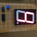
Step 8: Probing the First Digit


For probing the first digit, install the IC 4049, 555 timer, and the IC 4518, 4071 and 4081 from the column that corresponds to the proper digit. Once installed the respective ICs, connect the 9V battery so that you can probe it by manipulating the switch.
Step 9: Uninstalling All of ICs

Before uninstalling the IC 4049, 555 timer, 4518, 4071 and 4081 previously installed, disconnect the battery so that you can continue with the connections to the other digit from your project.
Step 10: Continuing With the Project


For continuing with the connections to the other digit, connect the outputs of the LEDs to the corresponding OR, AND, and NOT gates while you connect to GND and to +9V respectively for each IC.
Step 11: Completing the Project


For completing the project, instal all of ICs and 9V battery. Next, manipulate the switch so that you can observe the results on the respective displays of LEDs.


