

Introduction: HestiaPi Smart Thermostat FR4 Case


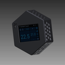


HestiaPi is an open Smart Thermostat for your home.
It runs openHAB on a Raspberry Pi Zero W and includes a touchscreen, temperature/humidity sensor and relays that get powered directly from the existing wiring of your house.
Our project has been running for a few years now with many changes coming from the community.
Wanting to make it accessible to everyone, we designed the case to be 3D printable in order to share the design but it turns out 3D printing is not everyone's cup of tea and definitely not for everyone's pocket.
Trying to find an alternative to 3D printing that looks good, is fairly cheap, sturdy and comes in at least black or white options we thought of redesigning the case as flat sides, made of PCB material that solder together.
The results are looking really good and should have been with us a few weeks ago to share the results with you but due to Corona virus, they are really delayed.
Design considerations
While designing it we had to keep various aspects in mind:
- Structural: The case had to be sturdy and protective
- Mechanical: The case had to be able to open and close easily and secure the actual circuit's PCB in place
- Thermal: Heat dissipation is an important area here as the circuit needed free air flow for cooling and the temperature sensor should not be affect by it
- Electrical: A ribbon cable, used in previous design, often caused problems to some users so we had to incorporate this into out case.
The Parts
The case consists of the following parts:
- Front cover with the opening of the LCD
- Six side walls for ventilation
- Backplate to secure the case to the wall and also hold the circuit's PCB
Step 1: Assembly


Each side that had to be soldered to the adjacent side had a thick area of copper that could easily be "glued" together with solder. The only thing that needs attention here is aligning the 2 parts first, then adding a drop of solder in one end, making sure you are still aligned correctly, then adding another drop to the other side.
Once you are sure it is correctly slowly solder the rest.
The six walls solder with each other and the front.
Then six male and six female pin headers (2x1) help "locking" the front cover to the backplate. Checkout the tiny rectangular solder pads on the white designs.
For securing the actual circuit PCB on the backplate, an additional solderable threaded PCB mount (image of silver barrels) could be soldered on the backplate. Alternatively brass M2.5 nuts can be used hence the four hex solder pads on the white design.
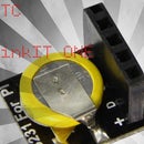
Last but not least, the backplate incorporates the wiring for the sensor. 4x1 pin headers help the connection of the PCB on one end to the sensor (BME280) on the other end as far away and close to the lower walls.
Step 2: Before You Go...
To find more about our greater project, not just its case, head over our previous instructable or simply our website with all the latest info and downloads to make it yourself.
The design is not final yet but will be released on our website/Github repo once it is tested and approved.
We used lots of ideas from this post which may cover other needs if you plan on making something else yourselves. Share the love :)
If you like our work, feel free to vote for us in the competition at the top.
Step 3: UPDATE: Finally It Arrived!


Some of the parts arrived today and I quickly soldered one together!
Will try and get some more photos for you...

Participated in the
PCB Design Challenge


