

Introduction: Home Automation Controller for Electric Car Charging


Not long ago, a friend of mine built a controller box for his electric car which used a mechanical timer and a hacked wireless remote. It sounded like a great idea, and since I already had a Home Automation system, could I build something similar integrating Home Automation? I set to work building it. Here's how I did it, so you can too!
This Video shows the project overview:
And this video shows you step by step how I built this project:
The automation system allows for advanced control over starting and stopping electric car charging. This is extremely useful for Time of Use electric rates, avoiding Peak Electric Usage times, and other features such as future integration of solar into electric car charging. At the heart of the project is a Contactor. That's a high-power switch which can be activated by a lower power switch, or even one of a different voltage. I'm using a "smart light switch" to activate the contactor, and control the switch from my Samsung SmartThings home automation system.
CAUTION! This project involves working with 240V AC wiring. Please observe standard safety procedures while working with mains power.
Step 1: Tools and Materials


TOOLS & MATERIALS
To start with, I needed to gather the components I'd use for the project:
Samsung SmartThings hub or kit:
- Leviton Smart Switch:
- 2-Pole 40A Contactor with 120V coil
- Digital Multi-Display w/ Current CT
- NEMA 14-50 240V electric outlet or outlet to match your EVSE
- NEMA 14-50 Appliance Cord
- Colored LED Indicator Light
- 8"x8"x4" PVC Electric Junction Box
- Ground Bar (x2)
- 14 AWG stranded wire
- Female Solderless (Crimp) Female Spade Connectors
- #10 machine screws and matching nuts
For a complete list of items used in the project, including links, please visit 300MPG.org
I already had the Samsung SmartThings hub set up at my home (which was part of the genesis of the project.) I'd previously used the multi-display to add real-time monitoring to my solar and have been very happy with it. I also already had the appliance cord. The rest of the components were a combination of mail-order and picking up at my local home improvement store.
As for tools, they were mostly ones that would be typical to a shop.
- Screwdrivers
- Drill
- Drill bits - 3/16", 7/8"
- 2+1/8" hole saw
- Dremel rotary tool
- Pliers
- Wire Strippers/Crimper
- Punch
- Pencil
- Marker
- Speed Square
- Straight Edge and Ruler
On this project, I found a Dremel with a fluted spiral cutting bit in it worked well to cut out the square holes required for the switch and multimeter display. Rotary cutters can be a bit difficult to control, so they work best with jigs, fences, and guides.
Step 2: Layout, Cut-outs, and Mounting


The first step is simply to layout the components.
On the back of the cover for the 8" electric box, I laid out the components in an order that made sense. Since the EVSE would hang down from the electric outlet, I made sure to plan the NEMA 14-50 outlet to be on the bottom of the box. The switch would be on the lower-right, the ammeter display above that, and the power indicator light in the upper left. The contactor would go in about the middle of the box, so there would be plenty of room for the wiring.
I marked the light-switch and electric outlet by tracing their covers. I traced the ammeter display directly. The indicator light uses a 7/8" hole, so I simply marked its center. I used my speed square to make sure the components would like up with each other.
Drilling the hole for the power indicator light was simple - just put in a 7/8" bit and drill. The other components were a little more complicated. The NEMA 14-50 outlet uses a 2+1/8" hole. Fortunately, I had a hole saw that size. Unfortunately, it didn't have a center bit. After scratching up the underside of the box cover, I realized that I could drill a 3/16" hole, and then just slip the hole saw over that to keep center.
The ammeter display and the light switch were both rectangular holes. To cut those, I used a Dremel tool with a fluted spiral cutting bit. Once the hole was cut, I cleaned up the edges with the few strokes of a file. Unfortunately, the light switch hole was a little irregular and it's the only component which doesn't have some sort of lip or edge that helps hide the hole!
Once the various holes were cut, I could put the components in and mark where their mounting holes were. I then drilled the holes and used #10 machine screws to mount the components.
Step 3: Wiring

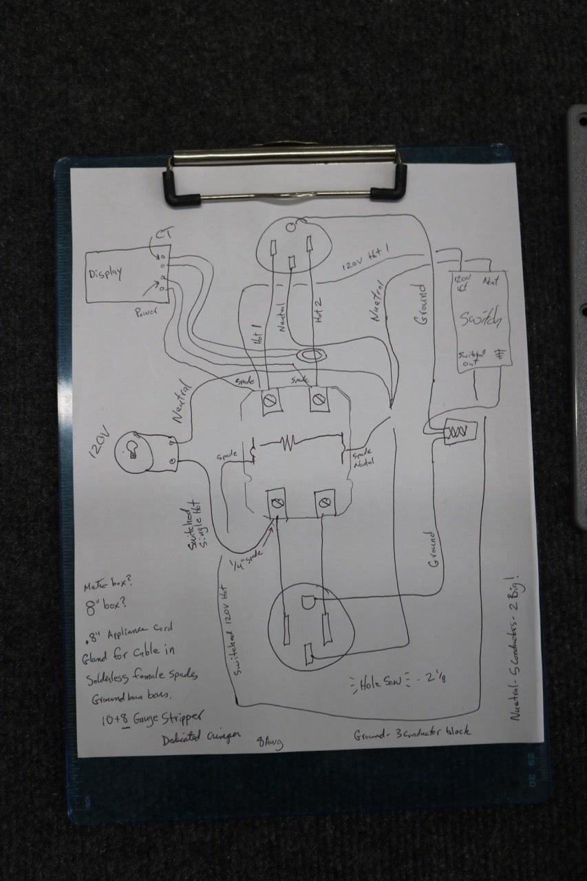


Next, I starting wiring up the project.
I cut several pieces of heavy wire off the appliance cord. Those are 6 gauge - very heavy, and able to carry plenty of current. I used those wires to connect the Contactor to the NEMA 14-50 electric outlet. I connected the red wire to the contactor and then slid the Current Transducer over that wire before connecting the other end to the NEMA 14-50. Next, I connected the heavy black wire from the other pole of the contactor to the NEMA 14-50.
For the ground and the neutral, the project will have a number of conductors coming together. So I mounted down two bus bars to box cover, the ground on the right and the neutral on the left. This is similar to connections inside of a home electrical breaker box. I connected the ground of the NEMA 14-50 to the ground bus and the neutral to the neutral bus. Because those wires are so heavy, I pre-bent them with pliers so the shape would easily fit from the electric outlet to the bus bar.
(NOTE: I made a mistake here on mounting the bus bar. Please see footnote at end of this step for more.)
The multi-display uses 4 connections. Two of those are already the very small wires coming off the CT. The other two are power for the display. I cut two pieces of wire and crimped a female spade connector onto each. Each of those spades went to the male spade terminals on the bottom end of the contactor. That end of the contactor will be where the main power cord connects. That way, the display will always have power. I screwed down the other end of the two wires into the display using the diagram on the back of the device.
The Power Indicator Light runs on 120V. I ran one black wire, with a female spade connection on one end, from the switched side of the contactor to one terminal of the light. The other terminal of the light got a wire running down to the neutral bus. That completes a 120V circuit. The light gets 120V and shows that the switched 240V outlet is powered up.
The smart switch used a few short pieces of 14 AWG wire. The black hot wire was connected with a spade connector to the always-on end of the connector. The white neutral wire runs to the neutral bus. The ground wire runs to the ground bus. The "switched output" wire of the switch gets a crimp-on spade connector and then is plugged in to the coil connector on the contactor. The other contactor coil connection gets a wire routed to the neutral bus and completes a 120VAC circuit to activate the contactor.
Footnote: While all the connections were made properly on the neutral bus, I originally used machine screws going THROUGH the enclosure. This means that electrically the heads of the screws on the outside of the box were connected to the neutral. Although neutral and ground are CONNECTED together back at the main circuit breaker, the neutral is still considered a current-carrying wire and must be insulated. After realizing my mistake, I removed the neutral bus and reinstalled it connected only to an insulated spacer.
Step 4: Testing

At this point, the project was ready for testing.
I temporarily connected the appliance cord to the two hot connections at the contactor, and the ground and neutral to their appropriate bus bars. I turned off the circuit breaker for the wall outlet, plugged in the appliance cord, and turned the power back on.
(Please note that at this point LIVE 240V power is flowing, and care must be taken to avoid contact with live conductors.)
The Remote Control Box powered up, and the backlight of the display turned on. The small power indicator on the smart switch came on as well. I pressed the switch and heard the "ka-lunk" of the contactor snapping shut. At the same time, the Power Indicator Light came on. I used my multimeter set to AC voltage to test the output of the NEMA 14-50 electric outlet. It checked out just fine.
Step 5: Connecting to Samsung SmartThings


I figured that now would be a good time to connect the smart switch to my Home Automation system - Samsung SmartThings. Following the instructions that came with the switch, I pressed and held ON on the switch for 7 seconds, and then pressed it once. The tiny LED on the switch indicated that the switch was now in the correct mode to join my automation system.
On my phone, I opened the Samsung SmartThings App. I selected "Add a Thing". After waiting a few seconds, the switch appeared in my app. (Unfortunately, on the video, my camera battery died right when this happened, so I didn't get to fully document how simple and seamless it was to add the device.)
I tested the switch and was able to turn it on and off with my phone. As I did, the contactor and thus indicator light and power at the 240V outlet would turn on and off. IT WORKED!
I turned off the breaker and unplugged the appliance cord to the Remote Control Box.
Step 6: Adding Appliance Cord


Next, I had to drill a hole to thread the appliance cable into the box. I had a cable clamp which would go in that hole and tighten down around the cable. I realized that I didn't have a drill bit that exact size. I did have a circle-cutting attachment for my Dremel. On the bottom of the box, I would NOT center the hole for the cable. There's a rib there for the screw hole. I'd need a nice flat part for the cable clamp. Instead, I decided to center the hole on the left side of the bottom of the box. I drew kitty-corner on the left half of the box to find center, marked it, and then drilled a 3/16" hole. Then I used the Dremel with the spiral cutting bit and circle attachment to cut the hole in the box.
I inserted the cable clamp into the box, and tightened it down with the conduit ring on the back side.
I pushed the appliance cable thought the clamp, made sure I had plenty of reach with the wires, and then screwed down the collar to hold the cable in place. I connected both hot wires to the input end of the contactor and the ground and neutral to their bus bars.
After that, I tucked everything in, pushed the cover down onto the box, and screwed down the cover.
The back of the box had holes to add some mounting tabs. I placed the tabs on the corners of the box and held them in place with large screws included for that purpose. With that the Remote Control Box was complete.
Step 7: Wall Mounting

When considering where the box should go, I took into account proximity to the existing wall 240V electric outlet as well as who would be charging the electric car. My daughter is 7 years old at the time of this writing. She's been excitedly plugging in the car for the past two years. As a 7-year-old, she's not that tall. So, I made sure to mount the box relatively low.
(On a side note, not long ago, I was injured and in a wheel-chair for some time. Being disabled makes a person take certain things into consideration which one otherwise might not, including the height at which equipment is mounted.)
Once the location was decided. I mounted the box to the wall. It went right next to the existing wall outlet, not too high. This also aligned the right two mounting holes with a wall stud, so the box would be very solidly mounted. I put in one screw to just hold the box to the wall. Then I placed my level on top of the box, made sure it was level, and then marked the screw holes. I pre-drilled and then ran wood screws through the box into the wall.
Step 8: Programming and Use


I plugged in the appliance cord from the remote box to the wall and then turned on the power at the breaker. I plugged my EVSE into the box. In this case, I'm using an Amazing-E EVSE to charge my car. Using either the switch on the box or the app on my phone, I could turn the EVSE on and off.
Next, I started experimenting with some of the settings in my Samsung SmartThings app.
I could easily add a timer. For example, I can program the switch to turn on late in the evening, let's say 11:00PM. That allows me to plug in my car right away when I get home. The power will be off and the car won't charge. At 11:00 PM, the power will turn on and the car will start charging. This allows me to easy AVOID charging during the "Peak Time" in the evening when everyone else is coming home and beginning to use plenty of power, turning on lights, making dinner, and otherwise using a lot of power.
In my area, much of our electricity comes from coal-burning power plants. At night, they are underutilized, but still have to idle. That's a great time to use electricity - when pretty much nobody else is. Many power utilities offer Time of Use plans in which there's a heavy discount to use electricity at night. Often, the cost is HALF. Using the Remote Control Box, a person can set up car charging only during these OFF-PEAK times to save a substantial amount of money. The app also makes it easy to program certain days of the week and all sorts of other variables.
I intend to experiment more with some of the other features of the home automation system to maximize solar energy into my electric car and avoiding peak energy use power from the grid.
If you want to see how much power my home solar is making, you can view that at: https://pvoutput.org/intraday.jsp?sid=60383
While I designed this project for controlling electric car charging, there's no reason why it couldn't control other high-power devices. Perhaps you need to remotely control "Clark Grisworld" Christmas tree lights?
Whatever your use, this project gives you control through your Home Automation system!


