

Introduction: Home Automation Using Esp826612E,NodeMcu and Blynk App


Hey guys , how are you doing?. This weekend when I was pondering about what exciting I can build ,on the Esp NodeMcu board, I was struck by an idea, why not build an awesome home automation module which is compact and packed with features to help you control your home appliances from anywhere in the world.
Sounds Exciting right? and there is one more cool feature which I have incorporated in it is the Timer Feature wherein you can set the time for your appliances to switch on/off. How cool is that!!
This also includes an Lm35 temp sensor to monitor temp of your house/surroundings and take necessary action based on it.
So lets jump into the project and enjoy building this awesome home automation module which you can fix it any home to make it into a smart home at a cost of not more than 16$.
Step 1: General Overview of the Project

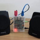
This project is now at the nascent stage and for development purpose we are using led's to indicate the switching on and off of appliances. You can add a relay and control a real home appliance too. having said that lets see what actually it does.
##The first and the foremost thing which it does it is detect motion and in case of any motion detected , it sends a mail to your configured inbox saying that a intruder is detected or any custom message which you would like to send it to you.
##Then it detects and monitors the home temperature and lets you know the temp reading right at your phone and can send of a alarm via a buzzer in case of any emergency.
##Finally It has a pair of flasher leds's which can be used in case of a power failure . You just have to click a button from your android phone and the flasher flashes obviating the need to search your home for candles, emergency lights when you have the technology right at your palm
## It also gives you information about RSSI( Received Signal Strength Indication ) of the Wifi signal which this device is receiving.
## You also see the Local Ip address to which the device is connected so that, you are aware that your device is connected to a safe known Network!!
So I hope that you guys have got an eagle eye's view on what we are going to build and what all function it performs
Step 2: Things You Will Require:


So building this module requires a list of component and here is the list.
1. ESP8266 NodeMcu board
for my friends in India :follow this link if you want to buy
http://www.amazon.in/ESP8266-NodeMcu-WiFi-Developm... and for my buddies in around the world: http://www.amazon.in/ESP8266-NodeMcu-WiFi-Developm...
2. 4 - Led's 5mm
3. LM35 Temp sensor
4. Piezo buzzer
5. Relay Module
6. Bread Board
7 Connecting wires and a stripper
8. PIR Motion Sensor
9. Android Phone with Blynk app installed in it.
******Optional*********
1 General Purpose PCB
2. Solder Iron with Lead and fl
This two can optional requirements are necessary if you plan to make a prototype of this project.
Step 3: Circuit Diagram:


In this step we will see how you should connect the sensors with the Esp8266 12e Board.
This instructables assumes that the user knows how to setup up NodeMcu board with Arduino IDE. If you are not aware , not to worry
just check my tutorial on how to get started with Esp8266 12E
www.instructables.com/id/Simple-Led-Control-With-Blynk-and-NodeMCU-Esp8266-/
One more important things before we jump into the circuit diagram is the Pin diagram for the NodeMcu board. you can also refer it in the photo attached.
For better understanding I have attached two files based on fritzing. One is a circuit diagram on Breadboard and another is a Schematic Diagram
Note: That Breadboard View is given so that you are able to get the overview of the connections. I would recommend you to see the Schematic and then build your project
Hope the circuit is clear.!
Step 4: What Is Blynk??

Blynk is a Platform with iOS and Android apps to control Arduino, Raspberry Pi and the likes over the Internet.
Blynk was designed for the Internet of Things. It can control hardware remotely, it can display sensor data, it can store data, vizualize it and do many other cool things. It's a digital dashboard where you can build a graphic interface for your project by simply dragging and dropping widgets. It's really simple to set everything up and you'll start tinkering in less than 5 mins. Blynk is not tied to some specific board or shield. Instead, it's supporting hardware of your choice. Whether your Arduino or Raspberry Pi is linked to the Internet over Wi-Fi, Ethernet or this new ESP8266 chip, Blynk will get you online and ready for the Internet Of Your Things.
Step 5: Setting Up Widgets in Blynk App


So in this step we are going to build an awesoem GUI with Widgets provided by Blynk and we are going to setup all the virtual pins so that our project is ready to be controlled by phone. Excited!!!
For More basics into getting started with Blynk from scratch and configuring the Esp board in Arduino IDE visit my
instructable:
https://www.instructables.com/id/Simple-Led-Control-With-Blynk-and-NodeMCU-Esp8266-/
I highly recommend to visit my above instructables to those who are a novice , when it comes to working with Blynk .
So the once you are familiar with how to add and configure Widget, on the Blynk App, then it is only a cakewalk to build this project.
So assuming that you guys know how add widgets in Blynk, Just refer to the Screenshots. It contains all the images which are required to build this project.
Step 6: Code Basics
So in this step I will explain on how little on what I have done in the code and you can find the code attached at the end of the instrucatbles.
In the Initial lines of code I have initialised all the pins required for the home automation project
Then an important function called Blynk.begin(auth, "SSID Name", "*******") is called. In its parameters you should give in the SSID name and password of your network .
Then there is a function called Blynk.run(). This is the most important function as this function keeps on listening for data and command from the blynk server which in turn receives the command from the Blynk app on your smartphone.
Another important function to find the RSSI strength is the WiFi.RSSI() . This function provides the signal strength
The expression dBm is used to define signal strength in wires and cables at RF and AF frequencies. The symbol is an abbreviation for "decibels relative to one milliwatt," where one milliwatt (1 mW) equals 1/1000 of a watt (0.001 W or 10 -3 W). This unit is commonly used in test laboratories
To find the Local Ip address to which the device is connected we use WiFi.localIP();
A very important concept used here is the Virtual Pins. What are Virtual Pins?
Virtual Pins are designed to send any data from your microcontroller to the Blynk App and back.Anything you connect to your hardware will be able to talk to Blynk. With Virtual Pins you can send something from the App, process it on micro controller and then send it back to the smartphone. You can trigger functions, read I2C devices, convert values, control servo and DC motors etc.
Virtual Pins can be used to interface with external libraries (Servo, LCD and others) and implement custom functionality.
You can send any data from Widgets in the app to your hardware.
All Controller Widgets can send data to Virtual Pins on your hardware.
For example, code below shows how to get values from the Button Widget in the App
BLYNK_WRITE(V1) //Button Widget is writing to pin V1
{ int pinData = param.asInt(); } //When you press a Button, Blynk App sends 1 On the second click - it sends 0
With this you can perform any action you want . For ex you keep a led on pin 13 and this should glow when you press Virtual Pin V1, Then the code you should implement is
BLYNK_WRITE(V1)
{ int pinData = param.asInt();
if (pinData==1)
{
digitalWrite(13, HIGH)
}
}
The above Mentioned concepts have been implemented in the code. hope it is clear :)
Step 7: Execution:


We have reached the final step of our process and now just follow the below steps
1. Plug in the board and upload the program
2. While uploading the program do not forgot to put correct SSID and Wifi name
3. Upload and wait for a while , till the sensor is stable and then open the com port , you will see the status , that Blynk is connected to the internet
4. Once it is confirmed, then unplug the device from the PC and power it up an 5V Dc source and enjoy controlling your home appliances
Yahooo we have built an awesome project using NodeMcu.
If you guys have any doubt , feel free to contact me:)
Till then Have a nice weekend and
Happy Inventing!! :)


