

Introduction: Home Water Cascade With NodeMCU and Blynk - "Salto Angel"


Introduction
This project was inspired by several similar projects that you can find on the web. However, we will build a "waterfall" in the house that can be controlled by a NodeMCU microcontroller using the BLYNK IoT application. Through the cell phone, we will be able to manually activate the lights and the pump as well as program the operation at a certain time, for a desired period of time.
I recommend a youtube video of Kanelorocks Olivares that is very didactic and shows how to build a cascade in which I was very inspired. And that can teach you how to handle concrete and other construction techniques. It is in Spanish but worth seeing.
In the attached video you can see how we build ours. I hope you enjoy as much as I do.
If you have any questions, do not hesitate to contact me.
Supplies
The quantities of material needed will depend on the size of the waterfall you want to build. Ours is 1.2 m wide, 1.0 m high and 0.5 m long.
For the cascade:
- 1 plastic tray 0.8 m wide, 0.4 m long and minimum 0.3 m deep.
- 12 paving stones
- 8 clay bricks
- 8 curved pavement concrete bricks
- 5 bags of 25 kg of concrete 1: 2: 3
- 3 m x 2 m of plastic film with 2 mm thickness
- 3 m of galvanized metal mesh
Hydraulic installation:
- 1 minimum flow aquarium pump 2 m high
- 2 m of PVC pipe 1/2 inches diameter
- 3 x 90 degree PVC connection
Electrical Installation:
- 3 m of Electric Cables
- A piece of rubber hose
- 2 x 2" PVC connections for the bulbs
- 2 x 50W Led bulbs
Decoration:
- Acrylic Ink - white, black, red
- Hydrochloric acid to age the concrete (please handle it carefully as the acid can cause burns to the skin and eyes.)
- Some plants for decoration
For your safety:
- Rubber gloves
- Security glasses
- Overalls
Step 1: Building the Cascade


Hard work
I hope you know how to handle concrete mass. Not too wet or too dry.
- Dig a hole with the dimensions of the tray to make the pool and when finished, insert the plastic tray on place,
- Accommodate the cobblestones at the back of the tray, in 3 levels so that it looks like a waterfall.
- Before covering with concrete place PVC tubes with the 90 degrees connection where the pump will stay.
- Concrete everything to keep them united and firm. Let dry for 1 day to continue work.
- Place 8 clay bricks on the sides, at different levels, like a staircase. Fill everything with concrete. Let dry for 1 day.
- Place the curved concrete bricks on the front edge and concrete them. Place the plastic film that will prevent leaks, covering the entire piece and place the metal mesh on top. Use tape to keep them in place. The mesh serves to keep the concrete well glued to the surface. Cover everything with concrete.
- Place a piece of rubber hose on the front that will be used to pass the electric cable of the lights. Place the 2 PVC connections where the LED bulbs will be inserted. Concrete them all. Cut the PVC pipe at the height you want and place the 90-degree connections. Let's build a small pool above. Cover the PVC piece with concrete to hide it.
- On the front wall, where the water is going to fall, make some concrete shapes that look like stones. To hide the water pump, position it in its place, cover with plastic film and place paper behind. Make a stone of the necessary size with concrete.
- Once everything is built, we will "burn" with hydrochloric acid (muriatic). Be very careful with that. Use a mixture of 60% acid, 40% water and yellow earth for concrete. Mix well and apply above all the concrete. Let dry for a day.
Final Art
Now comes the final art. Use black, red and white acrylic inks to highlight the contours of the concrete parts that you want to look more like natural stones. This takes a while but brings a great impact. Let dry for 2 days.
Testing the operation of the waterfall. If your pump does, adjust the flow of water until the volume needed for a good waterfall.
Step 2: Building Electrical and Electronic Connections

Please take a look at the attached diagram for a better understanding.
If you do not know how to use nodeMCU and Arduino IDE, please enter this link - Microcontrollers Tutorial. You will find the explanations easily.
To make the electrical connections we need an outlet for the pump and another for the bulbs.
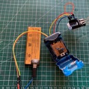
The two bulbs are connected in parallel. We will also need a double relay that supports 250V output and 5V input that will be connected to the NodeMCU. See the connection scheme.
Connect the NodeMCU PIN D6 on the Relay IN1 to control the pump and PIN D7 to Relay IN2 to control the lights. The NodeMCU will be powered with a 5V USB source.
All the VCC pins of NodeMCU has 3.3v except the pin VU (VUSB) that has the same 5V USB source. The relay will be powered by it.
Relays have two settings: "NO" - normally open and "NC" - normally closed. The "NO" means that when the relay is activated by the NodeMCU it will close the circuit and turn on the device. The "NC" is exactly the opposite. Let's use "NO".
And also the relays can be triggered by a low or high signal. That is, the NodeMCU sends through its PIN a value 0 or a value 1. In our case, we will use the one that receives value 0 to be activated.
Pump and the bulbs will be powered by 220V. Be careful with that. If you don't know how to manage high voltage electrical power ask for help.
Step 3: Using NodeMCU + Blynk


Controlling your Home Cascade
The control of the operation of the waterfall will be given by a cell phone that connects to the NodeMCU through the attached sketch using the Arduino IDE and the Blynk application.
You can download the app from the Itunes Store or Google Play. It's free. But must "charge energy" to use each widget on your project. It's cheap.
If you do not know to use the Blynk application please enter on the site Blynk where you can find the steps to follow.
You can control the pump and bulbs manually, by pressing the button of each one of them or program an on and off timer that will activate both at the same time and will turn off when the time is up. An LED light will come on informing you that the timer is in progress and, as a complement, it will send you a tweet informing when it turns on and another one when it turns off.
Let's create the application in Blynk
- You must have a Blynk account and create the project. This will give you the "Auth Token" to copy it to the sketch.
- Add the first "Styled Button" button with the D6 PIN and control 1 to 0, such as Switch
Add the second "Styled Button" button with the D7 PIN and control 1 to 0, such as Switch - Add "Timer" on PIN V1, from 0 to 1. Then you can program the on and off schedules.
- Create RTC (Real Time Clock) so that the Blynk can know what area you are in.
- Create an LED on PIN V2.
- Create a "Button" on PIN V0, from 0 to 1, such as "SWITCH"
- And finally, create Twitter by adding your Twitter account to the Blynk.
Copy the Auth Token to line 15 of the sketch, put your credentials (SSID and Password) of your home network in lines 18 and 19 and upload it to NodeMCU.
If you want to put more automatic programming with the timer, simply add another timer widget (such as timer 2, for example) and copy and paste the section of the sketch that triggers it and reloads it in the NodeMCU.
Ready to start!

Step 4: Everything Is Working Fine


And that's how it was at the end of the project. We take about 8 days to conclude. The attached video shows you everything working fine.
Do not forget the plants on the sides to improve the decoration.
I hope you liked it.
Enjoy it.

Participated in the
Backyard Contest


