

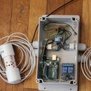
Introduction: Hook Up Exponentially More Digital Buttons to Your Arduino With a Binary Encoder


In this project, we'll use a method called Binary Encoding to let us read 7 digital buttons with only 3 inputs on the Arduino. If you want to expand this method, you can use 2nbuttons with only n pins.
One of the nice things about the Arduino, and specifically the miniature versions like the Nano, Micro, and Pro Mini, is its compact size. As a trade-off, these and other ATmega 328 based boards are limited to 14 digital I/O pins, compared to the hulking 56 pins of the Arduino Mega.
So what do you do when you build a project that requires buttons, and lots of them? I faced this problem when thinking about building a basic drum step-sequencer with 16 buttons to key notes.
A common solution is to use an array of resistors with your buttons and read them through and analog input. I'm not sure of the limitations in size of the method, but it has the downside of tying up precious Analog ports (used for pots and I2C). Additionally, it is not readily apparent how to use interrupts with this method.
Another common method is to use a separate integrated circuit, a multiplexer, to handle these large number of inputs. This is the "proper" and more powerful way to do it, but ultimately more complicated. This Launchpad Sequencer with MIDI output employs this method to drive 64 buttons and led's.
However, if all we want to do is just hook up a bunch of "dumb" buttons (a.k.a. momentary switches), there is a much simpler way to do this, which is to build a Binary Encoder. Adding only diodes to our button circuit, we can reduce the number of input pins we need to log2(number of buttons+1). In this example, we only need 3 pins to read 7 buttons. If we wanted to read 63 pins, we would only need 6 pins!
Step 1: About Binary Encoders


For a detailed explanation, check out the Electronics Hub article all about encoders: http://www.electronicshub.org/binary-encoder/ (the logic diagrams are from their article too)
In simple terms, a binary encoder is a digital logic circuit that, using OR gates, takes a number of inputs, each of which has a "value", and outputs this value in binary form when this input is activated. Importantly, it takes 2n input values and outputs them as a binary representation using only n outputs. It basically is converting a normal decimal number, represented by each of our buttons, and translating that into binary. This is done by mapping each input to activate a unique combinations of the outputs.
The reason we can pull of this huge reduction in the number of pins to read our buttons is that, since we are only using 1 button at a time (this is a limitation), the numbers of states of our button array is only equal to the number of buttons. Using the same number of buttons as inputs leaves a vast number of potential input combinations unused. However, if we want to be able to read different combinations of button presses, the number of combinations jumps to 2(number of buttons), and this method does not work.
Some Button to Pin Math and Comparisons:How many pins to we need using a given method?
n=(number of buttons), log() is base 2
- Binary Encoding: log(n+1)
- Largest pin reduction
- Only one button at a time
- Multiplexing: log(n)+1
- Requires an additional IC
- Works with multiple buttons
- Best for complex projects
- Keypad Scanning Matrix: 2*sqrt(n)
- Requires processor resources to scan the matrix
- Works with multiple buttons
- One Pin Per Button: n
- Simplest to implement
- Works with multiple buttons
If you're not familiar with the growth of these functions (it's usually used in analyzing algorithms), the important thing here is that log(n+1)<2*sqrt(n)
This doesn't quite drive the point home though. Let's see what happens if we want to hook up 64 buttons for an 8*8 touch pad:
- Binary encoding: log(64+1) = 7 (we need to round up to the nearest integer)
- Multiplexing: log(64) +1 = 7
- Keypad Matrix: 2*sqrt(64) = 16
- Pin Per Button: 64
As we can see, the Keypad Matrix won't work with a standard Arduino anymore, and using direct inputs won't even work with a Mega!
You may be wondering why the multiplexer and Binary Encoder aren't just log(n). For the binary encoder, we have to consider that the state of no buttons pressed takes up one of our binary combinations. For the multiplexer, we need log(n) inputs to select what input we are reading, and the +1 to actually read it.
Step 2: Enough Explaining, Let's Build the Circuit:


Although our circuit is logically equivalent to the logic diagram in the previous step, it doesn't quite look the same. Instead of symbolic "OR" gates, we are using diodes instead. In digital circuits, the OR gate is one of the only two gates that can be made with diodes alone.
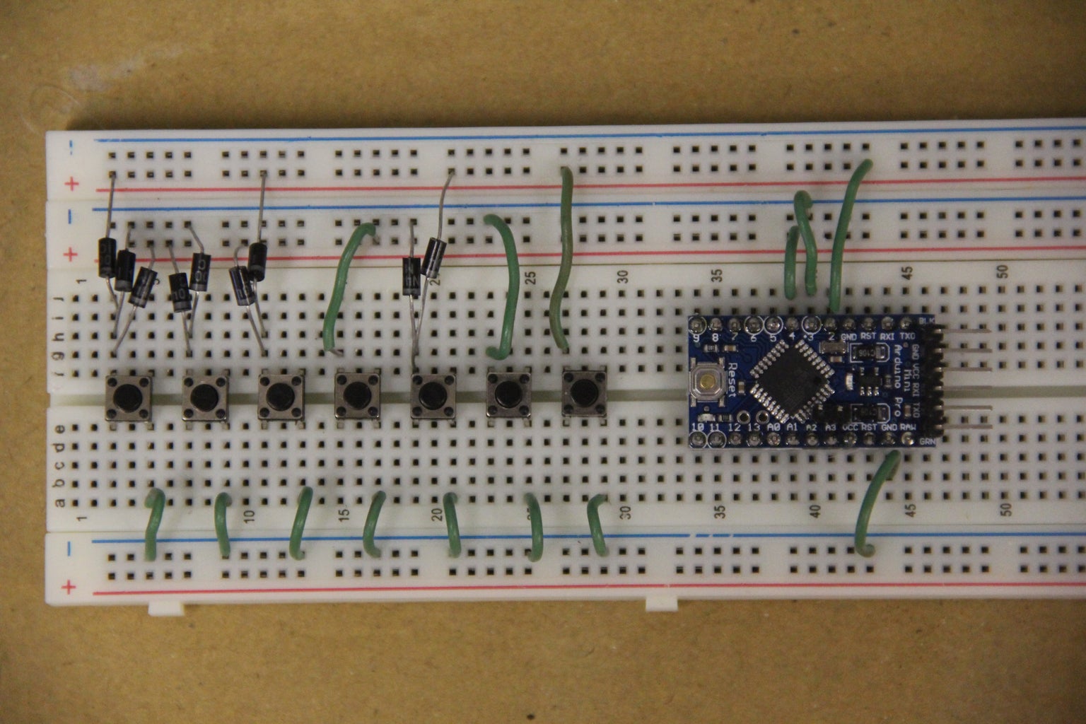
All we have to do is connect each button to our input pins in the binary code we want that button to represent. In between these connections between the input pin and the button is a diode. If we did not have the diodes, current would flow through the circuit connections and any time a button is pushed all the inputs pins would be triggered. The diodes keep our "logic" from propagating backwards through the circuit.
A couple of notes about how I've setup this circuit:
- I have the current flowing "backwards" compared to what we would expect. The natural state of the input pin is +5V (set by the internal pullup resistor), and pressing a button actually connects the pin to ground, bringing it to 0V. This is because if we don't use the Arduino's internal pull-ups and want to pull-down instead, we need to add our own resistors to the circuit. I have no idea if having your Arduino charge an array of 128 buttons or something crazy to 5V will cause bad things. You should try it anyways.
- We don't need diodes when or button is only signalling to one pin. The way the circuit is set up, when a button only leads to one pin, there isn't any issue with current "leaking over"
- We need a ton of Diodes. In fact kind of a ridiculous amount compared to the number of input pins we use on the Arduino. Just how many diodes? Theoretically, each of our n buttons is signalling to each of our log(n) input pins, meaning we need on the order of n*log(n) diodes. In practice it is not quite as much. We do not need to signal a 0 in binary, so we can divide the number of diodes in half. Additionally, single signal lines do not need a diode, so we can remove log(n) diodes.
- So we need (n*log(n))/2-log(n) diodes
- On our example circuit (7 buttons + the resting state), this is (8*3)/2-3=9 diodes.
- For a 63 button setup, this is (64*6)/2-6=186 diodes. That's a lot!
- So we need (n*log(n))/2-log(n) diodes
Step 3: Code to Read Our Buttons:
Here's some example code for reading our buttons. It will print out a integer number for each button, with 7 being nothing pressed. The method I'm using is to translate the status of the pins into a Byte, which will represent the value of the button pressed directly in binary form. This is the most straightforward way to do it. I've put in two different methods to read which button is pressed. One is to sweep through the input pins, and than assemble them into a byte. The other is to read to the pin register that represents our input ports (PIND for the regular Arduino).
When sweeping through the input pins, we need to read each pin, and then use bit shifting to construct our byte
If we just read the input register, we only need to make sure it's shifted correctly, and we're ready to go!
When you run the code, it will print out the button pressed in the serial terminal.
//Reading buttons through a binary encoder circuit
//2016 Michael Niemi
//MIT License
//
//

void setup() {
  Serial.begin(112500);
  pinMode(2 , INPUT_PULLUP);
  pinMode(3 , INPUT_PULLUP);
  pinMode(4 , INPUT_PULLUP);
}

void loop() {
  Serial.println(readSequential());
  Serial.println(readDirect());
  delay(100);
}

byte readSequential(){
  byte buttonId;
  for(int i=2; i<5; i++){
    if( digitalRead(i) == 1){
      //We will "add" the value of our pin to the byte. The << shifts it to the right bit, indexed by the loop
      buttonId = buttonId | (1 << (i-2));
    }
  }
  return buttonId;
}

byte readDirect(){
  //first pin we're using is 2, shift over by 2 (register starts at pin0)
  byte buttonId =  PIND >> 2;
  return buttonId;
}

Participated in the
Arduino Contest 2016


