

Introduction: How to Make the Easiest Breadboard Arduino Uno...EVER ! - the Breduino ! (& How to Upload Sketches Straight to It !!) With Additional Hardware Options - UPDATED - APRIL 2017


Step 1: Section 1 - Building the Regulated 5 Volt Power Supply !


"i used to label all my pictures within my instructables but it seems instructables.com doesn't show all the notes attached onto pictures with certain web-browsers so i will be only making a few notes Directly onto the Pictures but have the main instructions here in this typed section but for those of you that dont see any notes on the pictures either download and install another web-browser (i Use Opera and have Never had a Problem Seeing Notes on Pictures!) or just look at the notes in this typed-section of the Instructable Guide i have made !!
Observe the pictures carefully and take special note on the exact holes that the wire links & components go into, failure to follow the exact holes will result in this not working, i have painstakingly taken the highest resolution pictures as i could so there shouldn't be any problem viewing the pictures and if a component or wire link is being blocked by another component then i will have supplied a few pictures taken at different angles to show exactly where the placements of the components or wire links should be (this is something that wasnt on ANY of the websites i researched, darn it! lol) so look out for the different angles of pictures as they will be following each other, in organised fashion (im using different angled pictures so that anyone will be able to CLEARLY SEE what goes where!)
"ALSO i do explain every step in DETAIL so if you dont want to read too much just skip the reading and follow the picture instructions but i have included alot of info here - gathered from a great many different websites so reading this guide once fully wouldn't hurt but if you know what your doing please dont see this guide as an insult to your intelligence as ive put this together so that complete beginners like myself can easily follow these instructions !"
- Now, start by chopping up some single-core wire into the different lengths(or just chop them as-you-go!) so that your breadboard adventure for this project will go a little quicker and i have included a few pictures with a ruler to show all the wire links i used so you can roughly see what kind of lengths are needed but i dont get my wire links perfect 1st-time and it takes a few tries to get the right length but this is a good thing because it just means that with the colours of the wire links youve made whilst making them for this project means you can use them in many other projects as well in the future so it wont be a waste to try a few times to make the wire links!
After you have your wire links, its time to start !
The Power Supply:
NOTE: its VERY-Good practice to leave the 'Power' colours of the wire links as BLACK for the Negative (-) and RED for Positive (+) as it just makes life Soooooooo-Much easier later on to clearly & easily see which sections of the breadboard are specific to Power (Either battery or mains power!) !!!
Also i used a bit of Green Single-Core wire & its not in the first 3 pictures but you will easily spot it when its used (For the Tactile MicroSwitch!)
The Bottom-LEFT picture (Picture 1) is showing that you cut your wire lengths a little bit longer on both ends so that when you strip them you'll have enough bare wire to slot into the breadboard holes, The Bottom-MIDDLE picture (Picture 2) will show what im barking on about, lol, & the Bottom-RIGHT picture (Picture 3) is simply showing how to have the bends in the pieces of wire!
Now we finally start the Power Supply, lol !
NOTE:ALWAYS COPY THE RED & BLACK WIRE-COLOURS EXACTLY - You may Use any other colours for the rest or the wire-links as you please!
Start by looking at the picture below (Picture 4), and copy the wires exactly - NOTE: the Blue-Negative-Power-Line on the breadboard is at the TOP.
Here You have a Choice of Either Using:
- The SMALL Low-Power {300mA} TO-92 Type 5v Voltage Regulator or
- Another SMALL Low Power {300mA} TO-92 Type 3.3v Voltage Regulator
- The Bigger TO-220 Type {1Amp to 1.5Amp} 5v Voltage Regulator.
Voltage Regulators Used - Please Look At their DATASHEETS to make sure you get the pins in the right holes for connecting !!
L7805CV - 5v @ 1.5 Amps (1500mA)
KIA78L05 - 5v @ 0.15A (150mA) - This is NOW DISCONTINUED, Download Replacement 5v Low Power Datasheet below:
MCP1702-5002E - This is Now being used for all the Battery-Powered Kits, 5v @ 250mA
L4931CZ33-AP - 3.3v @ 0.25A (250mA) This is for special 3.3v Kits, carefully check the Datasheet so you know which pins are INPUT, GND & OUTPUT !
You will need: Both 47uF Electrolytic Capacitors & The 5v Voltage Regulator {Im showing the insertion of the Low-Power Voltage Regulator first (The KIA78L05) and this one is the SMALL TO-92 Type} Shown below (Picture 5), CAREFULLY Observe the Capacitor Legs going into the correct holes, the SHORTER LEG is the MINUS (-) and must slot into the NEGATIVE ( - ) Power Rail on the breadboard ! As for the 5v Regulator make sure the ROUNDED part is facing you and the flat side is NOT facing you, as shown by the Picture's View from above ! The picture Below_RIGHT (Picture 6) is showing the above installed parts from an angle to better see which holes the legs have been inserted into...
Looking at the Voltage Regulator in the above two pictures, from LEFT to Right the PIN-Labels are:
NOTE & WARNING: THIS IS FOR THE KIA78L05 VOLTAGE REGULATOR, YOU MUST CHECK THE PIN-OUT CONNECTIONS TO THE VOLTAGE REGULATOR YOU ARE USING WITH THE SUPPLIED DATASHEET LINKS ABOVE !
INPUT Voltage > GROUND > OUTPUT Voltage
(RED Wire) (BLACK Wire) (RED Wire)
Now i will show you how i use the BIGGER TO-220 Type Voltage Regulators with breadboards without damaging the holes and causing intermittent connection problems that these bigger type Regulators cause within the holes as their LEGS are very thick and not designed for breadboard prototyping so to prevent enlarging your breadboard holes this is what i do:
The 1st Thing i do is solder some short pieces of single-core wire onto the legs of the TO-220 Type Voltage Regulators (Assuming that you will always use this Voltage Regulator for prototyping purposes only and not be soldered into a permanent Arduino Project so its always Dab-Handy to have a few of these in your inventory of components!) and after soldering i use heat-shrink to cover up all the exposed bare-metal and wires that i do not want creating short-circuits when using these in my breadboards...
The pictures Below are showing the process of soldering the wires to the legs of the Voltage Regulators and i use RED wires for the INPUT and OUTPUT leg and BLACK Wire for the GROUND leg:
If you do this as well then you wont ever have the problem of having 'Enlarged Holes' in your breadboards and it will save you time and effort taking apart your breadboard to affect-repairs! Also as i had a few things to solder i usually keep a box specially for things that need soldering and wait until either i need them soldered or when there are more than 5 different items needing to be soldered so im not continuously getting my soldering kit out like a Yo-yo, lol
On with the instructable! lol
Next, bend ONLY ONE of the 0.1uF (100nF) Capacitors as shown in the small picture Below-LEFT (Picture 7) and insert it any way you like into the holes shown in the 2nd picture Below-RIGHT (Picture 8) but..... When a component can be inserted any way i always prefer to have the side that has the writing-on showing & facing me, thats only due to personal preference, its completely upto you !
Grab the 1N4004 Diode and bend it just like shown in the small picture Below (Picture 9) but Pay SPECIAL Attention to the Grey STRIPE and what side its on !!! This is added for Reverse Polarity Protection! Also grab one 1K Resistor (Colours: Brown,Black,Red,GOLD) and bend it like shown in the 2nd small picture Below (Picture 10), and Grab the GREEN LED and Closely Observe it has a FLAT-NOTCH on one side of it as shown in the 3rd small picture Below (Picture 11), This is the Cathode Side or MINUS ( - ) Side (NEGATIVE) and the LONGER Leg is the Anode PLUS ( + ) side , bend this as shown in the 4th small picture Below (Picture 12)... (Now if you want to keep the Parts-Count as Low as Possible you can choose NOT to use the LED or 1K Resistor in this step)
Once These 3 components have been prepared,insert as shown Below: (Picture 13)
Picture 14 is showing the newly completed section which is shown just after the heading, The Power Supply above!
DONE !!! - Take a little break as you've just Completed The Power-Supply Section of This Guide !! But Wait !!!!
Before Proceeding ANY FURTHER You must test this section and make sure it works before continuing and BEFORE ADDING anymore components just in case a mistake was made, and if a mistake was made it would be better to correct it here and now with no harm coming to the precious ATMEGA328P-PU Microcontroller as its not been installed yet, after-all when you've installed the ATMEGA chip you really dont want to blow it up by putting too much voltage through it do you ??? No. Didnt think so, lol !
Remember this Microcontroller Has a MAX Voltage INPUT of only 5.5 VOLTS (a range from 1.8v to 5.5v ONLY) so when your using a Voltage Regulator you'd be using anything from a 9 Volt to a 12 Volts for the INPUT Power Supply whether it be from the mains or a battery Pack and THIS would INSTANTLY KILL the Precious ATMEGA328P-PU Microcontroller that has the Arduino UNO Bootloader Loaded onto it leaving your Breduino Without a functioning Brain ! So...
Grab your trusty DMM (Digital Multi Meter) and test the GROUND and OUTPUT LEG of the voltage regulator to make sure it is indeed producing upto the 5v that we need ! You will need to connect up either a battery pack or a mains adapter (aka Wall-Wart, lol) to your breadboard Power BUT NOT AS YOU NORMALLY WOULD - Observe the Picture Below (Picture 15) and Notice WHERE PLUS ( + ) {RED WIRE} is being plugged into !! - NOT the red power line of the breadboard !!!
As you can See on the Picture Below (Picture 16) i am using a battery pack comprised of 8 rechargeable Energizer Batteries (1.35 Volts per Battery Fully Charged, approx, so 10.8 Volts Battery Pack being used - well within a recommended tolerance for the Voltage Regulator so that it does NOT lose alot of efficiency due to being overheated because if a higher voltage is being pumped in, the more-voltage being fed to these things - the less efficient they get but not to say they dont do thier job correctly of supplying 5 volts, no no no, its just that they would waste energy in the form of HEAT, Higher Voltage = More Heat produced by these things = power wasted as heat and a quicker drain on a battery pack !)
Also You can see in the Picture Below (Picture 17) that ive added a SPST Slide Switch to my Battery Pack because i like to insert the cables into my breadboards and have it not supply ANY Power to my components until i've Tripple-Checked Everything ive done so far because...
i have been told by the most well-knowledgeable of Electronics Experts that have PHD's and over 20 YEARS worth of education & Experience in Electronics that they also sometimes Get Simple things wrong by not taking the proper precautions and Double-Checking & Even TRIPLE CHECKING their work before Powering Up any Circuits so thats why the switch is on all my battery packs so i can connect it all up & check all my connections like:
- MAKE SURE that the Electrolytic Capacitors Polarity IS Correct ?
- MAKE SURE that the 1N4004 Protection Diode's Stripe IS Correct ?
- MAKE SURE that the LED Cathode ( - ) IS Correctly Placed in the ( - ) IS Correctly Placed in the ( - ) Breadboard power Rail ?
- MAKE SURE that the Voltage Regulator IS Sitting Correctly ?
Okay so a fellow instructables member, abqlewis, gently reminded me that in my magnitude of explanations and thoroughness that i had forgot to add a wire link that connects the top positive power rail of the breadboard with the lower positive rail of the breadboard, without this wire any current would travel through the microcontroller to get to any components that you would hook upto the Atmega Pins but with this wire link in place any components would get their power from the shared power from the rails on the breadboard and not rely on getting the power from through the microcontroller, this would have been fine for light to medium projects like LED projects and low power projects but anything heavy-duty would have put a strain on the chip...
Below, the Left picture below is where this page of the instructable finished and the picture on the right is the Red Positive wire link in place to connect both the top and bottom power rails (Many thanks for the catch abqlewis !!!)
Now you can take a quick break
Carry on into: Or
Section 2 - The ATMEGA328P-PU Microcontroller !Go Back To Intro
Step 2: Section 2 - the ATMEGA328P-PU Microcontroller !


- Ceramic-Resonator-Type that has 'Built-in' Capacitors OR
- You can have the Quartz Crystal Metal-Tin-Can-Type but with this type you will also need to install two 22pF Ceramic Capacitors as well !
Also i had copied directly from the ATMEL Datasheet to display the EXACT pin connections of the microcontroller and also a picture from the internet showing clearly what pin connections the Arduino Corresponds with the Pin Connections on the Actual ATMEGA328P-PU Chip ! Also the ATMEGA168 has the same pin-connections as the ATMEGA328 just for your information !
***** Always Always Always CHECK and DOUBLECheck the pin connections on the LASTThree Pictures in this step's picture list, refer to the one above to know exactly where you are connecting the Wires onto the microcontroller and the LAST Picture in the List Shows you how to SAFELY Bend The ATMEGA328 P-PU chip's Pins so that they fit smoothly into your breadboard or IC Socket, also as this will better familiarize yourself with the pin connections AND when your ready to power up the microcontroller CHECKaTHIRD TIME that everything is connected as it should be from this 'ible ! *****
Okay here we go!
Start by taking the last 1K Resistor (Colours: Brown , Black , Red , GOLD ) as seen in the 1st small picture below (Picture 1) and bend is so it looks like the 2nd small picture Below (Picture 2) and insert it as shown in the pictures below (Picture 3)...
Next, take the BLUE LED and insert it as Picture 4 Shows making Double-Sure you see exactly which side the 'Flat-Notch' is on as you can see in the picture Below (Picture 4) and just in case you cant see it clear enough - look closely to the right-side of the LED below, thats the MINUS ( - ) LEG so thats the leg that the 1K Resistor Connects to:(Now if you want to make this to have a LOW-Parts-Count you can choose to not use the Blue LED and its 1K Resisotr but these two components are used to test the Breduino with the 'Blink' Sketch later on, but its completely your choice ! lol)
Now time to add my Blue wire-link - NOTE that the wire link will go from the POSITIVE Side of the LED ( + ), look at the picture Below Carefully (Picture 5) and notice that its sitting in the hole just above the (Anode, + ) POSITIVE Side of the LED and there are EXACTLY FOUR holes that this Blue wire-link skips before entering the 5th hole - THIS IS VITAL IT STAYS CORRECT !!! (This is Pin 19 on the ATMEGA Chip also known as Pin13 of an Arduino, Please refer to the 'Pin Mapping Picture' at the end of the pictures list or at the beginning of Section 2, THIS Section !)
--- *** !!! ATTENTION !!! *** ---
Now BEFORE PROCEEDING ANY FURTHER - THIS IS THE TIME TO SLIP ON an AntiStatic-Writband to make sure you do not accidentally destroy or damage the precious ATMEGA328P-PU Microcontroller as you go to Place it into the breadboard for this step and i have pointed out a good number of times the very-REAL-threat/s of ESD Damage on components that are susceptible to this kind of damage and if you know what your doing jus ignore me rambling-on and continue with this Guide but please note that without proper ESD Prevention - you could essentially damage your ATMEGA Chip and it necessarily wont show up straight away that its been damaged but could even take months before it fails completely so Prevention IS Better than a Cure i always say (Computer-Repair Background for me!) so as long as you observe these tips carefully there shouldn't be any problems...
A Quick Tip though:
I used-to repair my computers/laptops for over 10 years without EVER owning an Anti-Static Writsband because i ALWAYS used-to touch the computer's power supply metal housing BEFORE & DURING handling ANY sensitive devices susceptible to ESD damage AND NEVER move my feet after touching the computer's power supply housing - as i always had carpet on my floors and we all know rubbing your feet on carpet causes static electricity to build up and ive NEVER EVER had any device FAIL on me EVER - So it is Completely Possible to be safe in the use of these Microcontrollers without an AntiStatic Wristband BUT YOU MUST GROUND YOURSELF BEFORE & DURING TOUCHING such Sensitive Devices and the Anti-Static Wristbands are so very cheap nowadays i treated myself to 4 of them from China lol !!!
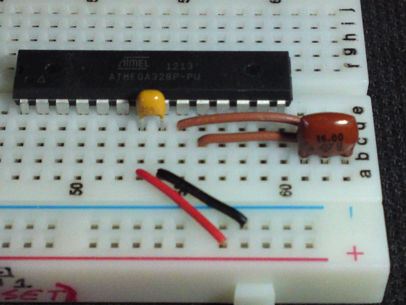
Take the chip out of its special Anti-Static IC Tube, these Microcontrollers Usually Come from the Factory with their pins slightly 'splayed' - what this means is that the pins wont line up totally with the holes on the breadboard or an IC Socket so you will need to SLIGHTLY & GENTLY bend them so that they are pointing straight down or even slightly inwards to have a good fit into the breadboard and one way to do this accurately like in the picture Below:
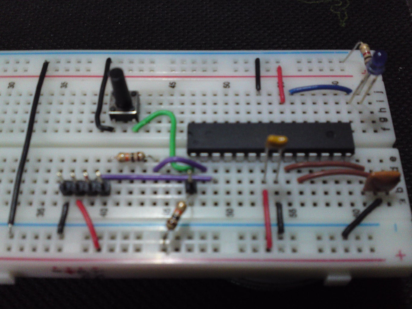
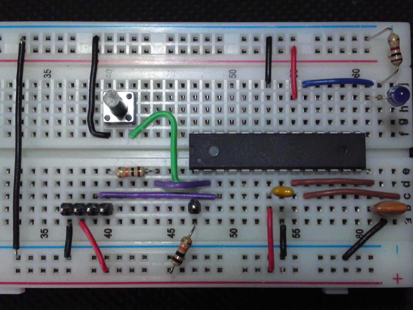
So Look at the picture below (Picture 6) and insert the ATMEGA Chip into the breadboard as shown Below MAKING SURE that PIN1 is inserted into the LOWER-BOTTOM-LEFT had-side of the breadboard (Click on Picture 6 in the LIST of pictures just under the title of: Step 2 Section 2 - The ATMEGA328P-PU Microcontroller ! above for notes displayed onto Picture 6)
Ok now grab the last 0.1pF (100nF) Ceramic Capacitor and place as shown in Picture 7 (into the holes where PIN 7 & PIN8 are on the ATMEGA Chip!) along with the two power wires also as shown (RED Wire to PIN7 & BLACK Wire to PIN8 of the ATMEGA Chip!)
Add the next Two brown wire links as shown in the 1st picture Below-LEFT (Picture 8) {into PIN9 & PIN10 of the ATMEGA Chip} - these are for your choice of installing either a 16Mhz Ceramic Resonator (with Built-in Capacitors) OR a 16 Mhz Quartz Crystal Resonator that must have TWO accompanying 22pF Ceramic Capacitors... Firstly i will show how to connect the Ceramic Resonator - place this as shown in the 2nd picture Below (Picture 9), these resonators you can place in any direction but i like to have the writing on the component facing me but you can place them how you please, placed into the 3 holes that are shown in 2nd picture Below-RIGHT..
In the picture Below (Picture 10) place a black Ground wire ( - ) as shown !
Now we will be installing the Quartz Crystal Resonator in place of the ceramic one, If you either dont have a Ceramic Resonator OR your project is a timing project that needs greater accuracy then the picture Below-LEFT (Picture 11) shows just after installing the two brown wire links and the Capacitor added on the picture on the picture Below-LEFT is the first 22pF Ceramic Capacitor and the Below-RIGHT picture (Picture 12) is showing the second 22pF Ceramic Capacitor in place...
The Below-LEFT (Picture 13) shows placing the Quartz Crystal Resonator - now - you can put these in any way round in the two holes its in but again, i prefer to be able to read the writing printed on the top of them but its completely up to you how you want to place it ! And finally the picture Below-RIGHT (Picture 14) shows adding the Black 'Ground' wire link and thats it for the part on Resonators !
So Now you Can Choose which type of Resonator you want to use or that comes with your kit !!
For installing the Tactile Switch (Which is used to either Reset the Breadboard Arduino or to initiate the "Manual Reset To Upload Sketches" which i will cover in the last Section of this Guide!), look at the TOP-LEFT picture Below (Picture 15) to start with placing a Green wire link like so, Then look at the TOP-RIGHT picture (Picture 16) Bend a purple wire link as shown - this makes it easier to place into the holes without interfering with any other wires, insert the switch as Shown in the BOTTOM-LEFT picture (Picture 17) then insert the Bent purple wire-link in the BOTTOM-RIGHT picture (Picture 18) ! { The GREEN wire link is first inserted into the PIN1 of the ATMEGA Chip & the Bent Purple wire link is inserted into PIN2 of the ATMEGA Chip which is the "RX" pin used for uploading sketches to the Arduino}
Now add a Black power (Ground) wire link as shown in the picture Below-LEFT (Picture 19) and the picture Below-RIGHT (Picture 20) is a close-up showing which way round the switch goes!
Now Bend both the 10K Resistors (Colours: Brown, Black,ORANGE,GOLD) as shown in the TOP-LEFT picture Below (Picture 21) & Bend the 10K Resistor as shown in the TOP-RIGHT picture (Picture 22) and insert the first 10K Resistor as shown in the BOTTOM-LEFT picture (Picture 23) Then add another purple wire link as shown in the BOTTOM-RIGHT picture (Picture 24) ! { Longer Purple wire link is inserted into PIN3 of the ATMEGA Chip which is the "TX" pin used for uploading sketches to the Arduino}
insert a Single-Pin-Header into the hole as shown in the picture Below-LEFT (Picture 25) & Insert the last 10K Resistor as shown in the picture Below-RIGHT (Picture 26) {This is the Breadboard Arduino's RESET PIN and this will be needed for Uploading Sketches the "AUTOMATIC SOFTWARE RESET" way as i really cant be bothered exactly "Timing" however many seconds it is to hit and release the reset switch when uploading my sketches so i always use the software-reset & its just done automatically as soon as i press upload-button on the Arduino IDE Software and not be EVER hassled with my sketches EVER FAILING to upload !!!}
The next 3 pictures Below (Picture 27, Picture 28 & Picture 29) are all showing what i do to these male-pin-headers to make them stay inserted into breadboards because they tend to pop out as soon as you insert them, you can see from the 1st Bottom-Left picture (Picture 27) the first three pins at the top don't have enough of their length to stay inserted in breadboards so observe the last pin which i simply pushed through the black plastic housing, do this to all the pins and they will make better connections in the breadboard for later Uploading Sketches! The Bottom-Middle picture Below (Picture 28) is showing a set of four pins that ive pushed through the plastic to make them an even length on both sides and the two sets of pins showing on the Bottom-Right picture (Picture 29) is showing how they normally come and my pins that are of (almost!) equal length of both sides!!
Next Insert the 4-Pin headers into position as the two pictures Below Left & Below Right (Picture 30 & Picture 31) These are showing that the 3rd Pin of the Headers is connected to PIN 3 of the ATMEGA Chip through the Longer Purple wire link and the 4th Pin of the Headers is connected to the 10K Resistor which is connected to PIN 2 of the ATMEGA Chip through the Shorter Purple Wire Link - DO NOT GET THIS WRONG or you wont be able to UPLOAD Sketches without having problems !!
Add the two power wires as shown in the two pictures Below (Picture 32) & (Picture 33) and the picture on the Right (Below) is Showing you what the pin labels correspond to on the 4-pin header when its time for Uploading Sketches in the last section of this instructable! ! !
Go and Make a Cup of Tea and Celebrate with a Slice of Cake or have a Kit-Kat as youve just Finished Making your Easy Breadboard Arduino Compatible and take a Well-Deserved Break and join me in the last Section after youve stuffed yourself with a treat, lol ! (British here so we like alot of Tea and cake, lol)
Jump into the final part of this Guide:
Section 3 - Uploading Sketches with 2 Different USB Modules!Go Back To Section 1 (Step 1)
Step 3: Section 3 - Uploading Sketches With 3 Different USB Modules!


Section 3 - Uploading Sketches with 3 Different USB Modules!
Now we will upload the 'Blink' sketch to the Breduino using Three different USB modules (These are the only ones i have !) and show how to connect these upto the Breduino and the pins needed to Upload Sketches:
The test Sketch we will be using is called 'Blink' and is found in the Arduino IDE under; FILE>EXAMPLES>BASICS>BLINK - this is the sketch we will use to upload to the Breduino !
The 'Blink' Sketch is a batch of instructions (Arduino Code) that will enable any Arduino-Based Hardware to Flash (or 'Blink') an LED that is Connected to PIN 13 of an Arduino/Arduino Compatible (Breduino!) and will flash the LED every 1000ms (ms=milliseconds) so basically every 1 second but this can be changed in the sketch to suit you!
Here are are a few of locations to find the correct Drivers for the USB Modules that i have used to Upload sketches:
FTDI Driver (Choose from: Windows, Mac, Linux)
PL2303 Driver (Choose from: Windows, Mac, Linux)
CP2102 Driver (Choose from: Windows, Mac, Linux)
Arduino IDE - Integrated Development Environment (Software) {Im using version 1.0.1 at the time of this instructable !}
NB: When on the Prolific Website to Download the Driver for the PL2303 USB Module , if ever asked to sign-in, just use their default Log-in Details:
Username: GUEST
Password: GUEST
NOTE:
ENLARGING PICTURES: When you want to see a Full-Size picture in this instructable, just click on the little pencil icon that appears on the TOP-LEFT hand corner of any Picture in the pictures list Just After the Step number, eg, Step 1, Step 2, Step 3 and find the picture in the list you want to enlarge from my references in my notes and then on the next page that opens up click the link just under the picture next to the words "original file:" and it will open up FULL SCREEN and show you all the glory of a nice beautiful high resolution image!! (BUT!!! if ANY of my pictures are NOT-CLEAR please please please tell me which picture & under which step and i will correct the fuzzy picture if any, many thanks!)
The USB BUB II
This has "Software RESET" capability {SEE NOTE1 after the instructable!} - so no more manually pressing the reset button when uploading sketches & no more 'Precisely Timing' the annoyingly-difficult time it takes to Press the Arduino's RESET Button (The Manual Reset- Way)...
Although this has the Auto-Reset feature it is a tad expensive.
The PL2303
The picture above is from a PL2303 module i modified to take advantage of the "Automatic Reset" of Uploading Sketches (Software Reset) so all you'd need to do is hit the Upload Button on the Arduino IDE Software and sit-back until your sketch uploads! See end of this Guide to find out how to get one thats already modified or if you'd like to modify it yourself then the link to those instructions are there too!!!)
This PL2303 USB Module isnt the easiest to modify as it involves soldering a capacitor leg to a very fine pitch SMD IC but if you can get your hands on some casting resin, this is what you can do with it, heres what ive done to protect the fine-pitch soldering on the PL2303 modules:
Also changed the Red power LED to a Blue one too !
The CP2102
The one pictured has already been modified for Auto Sketch Uploading but this module is the easiest out of all these USB TTL to Serial Modules to modify for Automatic Sketch Uploading, my modules now come heatshrink protected (Only the Auto-Reset Modules !) and as always with most of my gear, instructions are provided where needed !
NOTE:
These DONT come configured for Auto-Reset as standard (i Configure and solder the SMD parts myself) and if you havent bought a specific "AUTO-RESET-ENABLED" CP2102 Module then you will need to make the modifications on this board yourself, and you must use a 0.1uF Capacitor on the Reset Pin of the microcontroller - all parts needed are always supplied as well as the instructions being emailed to you ;-)Look for the CP2102 Modification you need to do to the Standard CP2102 Module at the end of this guide before the "Troubleshooting" Section !
NOTE 2:
If your CP2102 Module DOES NOT have heatshrink on it (Recently Coming with Heatshrink as Standard now) then its not configured for Auto-Reset unless you bought an Auto-Reset-Enabled CP2102 Module !!!
First we'll start Uploading the Usual 'Blink' Sketch Found in the Arduino IDE and using the Cheaper PL2303 USB Adapter:
Okay check out the picture Below - i have written onto the side of my breadboard the Exact-Pin-Connections You will need to enable you to Upload Sketches and Connect up the USB Adapter (PL2302)!
The picture below shows the RESET PIN on the Breduino along with the -, +, RX & TX on the left on the breadboard !
Now look at the pictures Below on all 3 of the USB Modules, their pin connections are always used in the same way to connect to your Breduino, just be sure that you connect up the correct pins to the breadboard!
For the modified PL2303 module(middle photo) Observe the Pin Connections and look at the very top Pin (The Soldered Extra Pin in GOLD , above the 3V3 Pin) - That is the Reset Pin that will need to be connected to the RESET Pin on the Breduino!
Basically you connect the pins like-for-like as shown Below:
Key:
NC = NOT CONNECTED
USB BUBII Breduino:
DTR To RESET PIN
3v3 (This is 3.3v) To NC * (See Note1)
VCC (This is 5v) To RED + Sign PIN on Breduino * (See Note1)
TXD To TX
RXD To RX
GND To BLACK - Sign on Breduino
PL2303: Breduino:
GOLD RESET PIN To RESET PIN
3v3 (This is 3.3v) To NC * (See Note1)
VCC (This is 5v) To RED + Sign PIN on Breduino * (See Note1)
TXD To TX
RXD To RX
GND To BLACK - Sign on Breduino
(AUTO-RESET-ENABLED VERSION)
CP2102: Breduino:
RST To RESET PIN
3v3 (This is 3.3v) To NC * (See Note1)
VCC (This is 5v) To RED + Sign PIN on Breduino * (See Note1)
TXD To TX
RXD To RX
GND To BLACK - Sign on Breduino
(STANDARD VERSION)
CP2102: Breduino:
DTR PIN*** To RESET PIN ***VIA A 0.1uF Capacitor !!!
3v3 (This is 3.3v) To NC * (See Note1)
VCC (This is 5v) To RED + Sign PIN on Breduino * (See Note1)
TXD To TX
RXD To RX
GND To BLACK - Sign on Breduino
Note1:
The Reason im choosing to power up the Breduino with the USB Module's 5v Output is just out of happenstance and you could just as easily substitute the 5v connection for the 3.3v Pin on any of the Modules Instead as it will work either way because the ATMEGA328P-PU Microcontroller is able to work from a range of 1.8 Volts to 5.5 Volts... (info found in the ATMEGA Chip's Datasheet!) ***BUT*** for 3.3v operation you will need to use the 3.3v Bootloader on the Atmega328 and also an 8Mhz Crystal !
Okay so now check a Third & Final time, after Checking of all the connections (CHECK, DOUBLE-CHECK and TRIPPLE-CHECK Every wire link & connection!) Open up the Arduino IDE software BEFORE plugging in any USB module and just Check a few settings to make this will work first-time !
Firstly we must select the correct 'Board' in the Arduino IDE, Look at the picture Below (Picture 8) and make sure that Under:
Tools>Board>Arduino Uno is selected... (My Kits all have the Arduino UNO Bootloader & others bootloaded upon request!)
Now you must select the correct "COM" PORT so the Arduino IDE will know exactly where the PL2303 USB Module is and where to send the sketch so after opening up the Arduino IDE just look at the picture Below, my computer didnt have any 'COM' PORTS in-use until i inserted the USB Module so i did that just to show you that a COM PORT will show-up in the Arduino IDE and you must select it and make sure there is a 'TICK' next to the COM PORT number as shown, mine is COM9...
But if you do have a few COM PORTS in use, just simply disconnect all wires from the USB Module and insert it in a free USB Port on your computer and see what COM PORTS open up in the Arduino IDE, then disconnect the USB Module from your computer and when the COM PORT Disappears from the
Arduino IDE then you will have found the correct COM-PORT-Number that is assigned to your USB Module !
Next look at the picture Below and make sure that the 'Programmer' is set to AVRISP mkII - from what ive seen in the few short weeks of learning about the Arduino IDE Software is that this setting is already set to AVRISP mkII but just in case it isnt, no harm in checking !
IMPORTANT NOTE:
After you've re-connected up all the wires from the USB Module to the Breduino again and BEFORE PLUGGING IN THE USB ADAPTER INTO A USB PORT --
- PHYSICALLY GO OVER THIS ENTIRE GUIDE AGAIN TO MAKE TRIPPLE-SURE ALL CONNECTIONS ARE CORRECT and that you have the Correct Polarity of components inserted the right way round into your breadboard like diode, LED's, voltage regulator, capacitors etc to avoid any problems/damage/errors to the Breduino or your USB Module !
I have followed this exact Guide and made another Breduino so now have TWO Breduino's that have the blink sketch uploaded to them and the PIN13 LED blinking away on both of them successfully so i know that this all works!(and constructive criticism is always welcome if you'd like to leave a comment below or Rate this a generous 5-stars or however many you think this guide deserves, i would be deeply honoured & grateful by this gesture!)
Now look at the picture Below, this is the location you will find the 'Blink' Sketch - select this Sketch and another Arduino IDE Window will open-up as shown in the pictures below...
NOW CONNECT the USB Adapter to a free USB Port on your computer and just double check that all the settings you've just gone through are still all selected and everything's ok ! ! !
Then click on the 'Verify' button which is the 1st Circle Shaped-Button (Under 'File') and it has a 'TICK' on it, After its been Verified, Click the 'Upload' Button right next to the Verify button as shown in the pictures Below:
if you've connected it all correctly the Arduino IDE Software will go through the process of 'Compiling' the Sketch and as soon as thats done it will start Uploading to the ATMEGA328P-PU Microcontroller that is sitting on the Breadboard and all you need to do is Sit-Back and watch the magic happen WITHOUT Timing however many seconds it takes to "Manually press the RESET Button" to Upload Sketches because Any of my Modified PL2303 or CP2102 USB Adapters will "AUTOMATICALLY" reset the Breduino (& EVERY other Arduino/Arduino Compatible!) so that the Sketch will Upload Successfully EVERY-TIME you UPLOAD a Sketch !!!AND WITHOUT adding a 0.1uF {100nF} Capacitor to the Reset PIN of the ATMEGA328P-PU Microcontroller !)
As soon as it finishes uploading your Arduino IDE Should look Like the picture Below with the Pin 13 LED Blinking away !!!!
*** If The Sketch didnt Upload Correctly Look Back Over ALL your Breduino Connections, Re-Check Everything and MAKE SURE you have installed the relevant DRIVER for your USB Adapter & like i said at the beginning of this Guide that Even the Experts Can Sometimes get the most simplest of things wrong in circuits (The honest ones who own-up-to-their-mistakes, lol !) NOT saying that im an expert in anyway as i also clearly stated that i am only still learning within The Wonderful World of Arduino but i know that this Breduino Works as i have tested this entire instructable on the very Breduino i have taken the pictures from and it works like a charm everytime! ***
Also something that i couldnt find so easily online through my good research assistant, Google, is a way to Take the Sketch off of the Arduino or Arduino Compatible
(Breduino!) or 'Cancel' the Sketch, so what i found buried in an Arduino.cc Forum was how to save my own sketch that 'Cancels' an Uploaded Sketch
All you need to do is go to create a new sketch in the Arduino IDE (File>New) and type this in:
void setup(){}
void loop(){}
Then SAVE this Sketch (File>Save or File>Save As) and you will also have what it took me HOURS and HOURS of Trawling through the Arduino Forums & Google to find a way for a beginner like me to kill an uploaded sketch from an Adruino/Arduino Compatible !!!
I hope you have as much fun making a Breduino for yourself with all the different options of how to create on of these for yourself and if its not too much trouble please
please please dont forget to 'Rate' this instructable between 1 to 5 stars at the very top-right of these pages as i would be most - grateful and deeply appreciative of that
and also please please please feel free to leave comments for constructive criticism or suggestions on this instructable at the end & many many thanks in advance !!!
NOTE1:
I Personally solder & Modify the PL2303 & CP2102 USB Modules in the Ebay Link at the Top of this page then finally encase the whole module in clear plastic, sand it with 3 different grades of sand paper ranging from Rough to Smooth then sand it again with smooth finishing with an expensive GLASSPAPER
(not sand paper) and finally polish it to a gleaming shine and i sell these on ebay fully made to take special advantage of the "Automatic Reset (Software Reset)" of the breadboard Arduino OR any other Arduino so all you need to do is simply press 'Upload' on the Arduino IDE Software and wait a few seconds until your sketch has uploaded without tediously and annoyingly failing to upload sketches "The Manual Way" by timing however many seconds it takes in order to press the Arduino Reset Switch and successfully uploading sketches!
I charge a reasonable price for all the work it takes to modify these modules and its alot of hard work as i dont have power tools and each module is crafted by hand so if your interested in one just visit my ebay page that has them being sold and not as expensive as any other Arduino USB TTL to Serial Converter & including postage & packing costs ! but so sorry, only selling to mainland UK at the moment folks so do apologize on that one!
How to Configure and Correctly Use the CP2102 Module
that was NOT Bought as an "AUTO-RESET-ENABLED"
module:
As these modules are ALL made in China, the designs for these modules are used for a great many other purposes (So i have seen online via google !) so to get them to work to send the all important Auto-Reset-Signal to Arduino Hardware is to use the DTR Pin NOT THE "RST" PIN as that will RESET THE USB MODULE !!! (BTW: For whatever reason the USB module needs to be reset like this is beyond me and i have no idea WHY the Chinese have designed this module like this in the 1st place !)
Okay So...... the Pin that sends the Auto-Reset-Signal to Arduino Hardware is called the 'DTR' pin, which stands for: DATA TERMINAL READY.
This USB Module is one of a very Very VERY Select Few, if not the ONLY ONE capable of modifying for our Arduino Uses with the least amount of soldering or SMD soldering !
This is where the All Important DTR pin is located on the USB Module and you can see from underneath the module that it says the 3 letters 'DTR' which can be better seen in the picture on the right, below (Above the pin named 'DSR')
And on the top side of the CP2102 module, the DTR Pin is the one with a box drawn around it near the tag "J3" as shown below:
The photo above-right shows where you will need to solder the supplied 1-Pin Male Header Pin to the DTR Pin of this USB Module to take advantage of the Autoreset Function of this module !
Once soldered, DO NOT USE THE RST PIN (ONLY THE BOUGHT AUTO-REST-ENABLED CP2102 Can make use of the RST PIN !)
Now here's how to connect:
1st Insert the Also Supplied 0.1uF Ceramic Disc Capacitor into two breadboard holes leading absolutely no-where lol:
Now link your newly soldered pin on the CP2102 module to the 1st Leg of this 0.1uF Capacitor, pictured below i am using a Blue wire to enter the hole of the 1st Leg of the 0.1uF capacitor:
And now Link the 2nd Leg of the 0.1uF capacitor to the RESET pin of the microcontroller as shown in the photo below (Another Blue wire, Lol !! ):
Now connect up your USB Module to the Breadboard Connections you made earlier and as mentioned earlier above for the STANDARD VERSION of the CP2102, here it is again:
(STANDARD VERSION)
CP2102: Breduino:
DTR PIN*** To RESET PIN *** VIA A 0.1uF Capacitor !!!
3v3 (This is 3.3v) To NC * (See Note1)
VCC (This is 5v) To RED + Sign PIN on Breduino * (See Note1)
TXD To TX
RXD To RX
GND To BLACK - Sign on Breduino
However... if you happen to have bought a PL2303 Module, There is an instructable on how to solder the 0.1uF (100nF) Capacitor on this great & awesome website and if you fancy trying to do it yourself and save a few pennies, a chap named LOG (Lazy Old Geek!) has helped us all out and made an extremely great instructable right HERE with all the procedure that i also used - so if you'd like to do it yourself then by all means feel free to do so, also as i only have a limited batch of these that i make and also i am severely mobility impaired so it takes a two weeks to produce only 7 of these as i dont have power-tools and my condition prevents me from making as much as i'd like but for those interested in acquiring one check out my ebay page where these are being sold HERE !
Troubleshooting
Now and again some folks get the Dreaded error message (& just in case you're wondering, yes this happens to me too lol):
:avrdude.exe: stk500_getsync(): not in sync: resp=0x00
When trying to upload.....
This error message is extremely cryptic...
Cryptic:
cryp·tic
: Having a meaning that is mysterious or obscure.
(or of a crossword-nature): Having difficult clues that indicate the solutions indirectly
Right, so all this error message tells us is that something is preventing the Arduino IDE from successfully uploading a sketch, but what it DOESNT tell us is where the Problem is !!!! - LOL !!!!
Okay so onto the Troubleshooting !
Check these things and make sure all is in order:
Breadboard Checks:
1. The usual suspect and a 'CURE-ALL' solution to breadboard setups NOT working as they should is always the AGE-OLD problem that many people Dont Know (95% of people, lol {And Yup, i was ALSO in that 95%, lol}) is the problem of ENLARGED BREADBOARD HOLES !!!!!
Due to using big TO-220 Type parts ( Voltage Regulators, MOSFETs, Power Transistors etc ), mainly because of these large pin components, breadboard holes are PERMANENTLY Enlarged and the best way to test if a breadboard hole has been damaged by a large pin component is to take the thinnest resistor lead (Leg) you can find, insert it into your 'Suspected' enlarged breadboard hole and then remove it ever so gently and if you feel any resistance of the resistor staying in the breadboard, then thats a good sign of the hole not being permanently enlarged... On the other hand, if the resistor Leg comes out of the hole without the breadboard putting up any sort of a fight to keep it in the hole, then thats a breadboard hole thats been permanently enlarged. Here's a how-to to fix that problem,but follow my tip in the Power Supply Section (Section 1) for what to do with the Big TO-220 Type components, Prevention is always better than a Cure ! ! !
2. Check the RESET Pin on the microcontroller has a 10K pullup Resistor going to +5v Rail on the breadboard.
3. Check that there is also a 10K Pullup Resistor going from the RX Pin of the microcontroller to an empty pin hole not connected to anything on the breadboard (This empty pin hole is where the RX from the USB Module plugs into !!!).
4. Check your cables for continuity, meaning check that they are not broken, you can do this using a DMM (Digital Multi-Meter), there is usually the sign of a Diode and the DMM beeps continuously when there is a connection all the way through a wire indicating that there is full continuity in that cable/wire !
5. DISCONNECT ANY WIRES GOING TO THE RX PIN OF THE MICROCONTROLLER While you are Doing the Upload (Meaning ONLY have the RX wire from the USB Module going to RX on the microcontroller !!!), here is a great Link after HOURS, DAYS, WEEKS & MONTHS of trawling through forum posts, all to NO AVAIL - AND some posts even go to mention THROWING AWAY your setup !!! huh, WHY throw away a perfectly good setup JUST BECAUSE "they" didnt know how to get it running or gave up troubleshooting lol ! Anyhoo, here's the link (MAJOR THANKS to Keith Parkansky for actually finding this out AND documenting it!)
http://www.parkansky.com/arduino-error.htm
USB Module Checks:
1. Do you have the correct Driver Installed for the USB Module you are Using from the Driver links at the beginning of Section 3 ?
2. have you tried uploading with:
TX from USB Module connected to TX on Microcontroller, RX from USB Module connected to RX on the Microcontroller
and/or/even/lol
TX from USB Module connected to RX on Microcontroller, RX from USB Module connected to TX on the Microcontroller
3. Have you soldered the 1-Pin Male pin header to the DTR Pin if using the STANDARD CP2102 module ?!?
4. Is your 0.1uF capacitor in place as it should be from these instructions ( Again, Only needed if using the STANDARD CP2102 Module ) ?!?
5.If you have a STANDARD CP2102 Module, you Need To Use The "DTR" pin instead of the RST Pin !!!
6a. Have you tried using a different USB Port ?
NOTE:About USB Ports:
The only sure-fire way i know of linking any USB to a pc is by linking a USB Extension cable (2 meters should be fine) from 'Only' one of the back USB ports on the computer leading to a USB Hub and make sure you buy a USB Hub thats powered (Has its own power plug!) and then use this for your USB useage that will sit comfortably on your desktop, give you plenty of USB ports and never ever have USB errors that windows usually gives when you try to connect digital camera's to USB ports as they try to always take about 1-2Amps yet pc USB ports are severely limited to 500mA (0.5A !!) !
I repaired computers for 13 years so this is all from experience lol
6b. Are you using a USB Port direct from your computer or a USB Hub ? Have you tried direct from your computer and, or, a USB Hub - if your computer's USB ports are not accessible - ?
Arduino IDE Checks:
1. Did you know that you can open up Multiple instances of the Arduino IDE ? Well this means you can open up the Arduino IDE 10 times and have them all up on your desktop !
Im not too sure if they will all work as needed like this and havent tested multiple uses like this but from my own humble experience, after the Arduino IDE has been open for a good 15-20 minutes of repeated FAILED tires to upload, it doesnt quite like this behaviour and so needs a restart, so Shut down all instances ( all open windows of the Arduino IDE ) of the Arduino IDE and then open it up again from fresh, this usually cures alot of the uploading problems too.
Windows Computer Users Checks: ( ! )
If your like me and have your Windows Computer running 24 hours a day, inevitably computers start experiencing Glitches or abnormal behaviour where something "should" work but "all of a sudden doesnt" - Guess What !!! Its because we're using a WINDOWS computer !!!!!!! !!!!!! !!!!!!
Mac & Linux users are probably laughing at this point lol....
1. Restart PC....... lol
2. Try Uploading Again
You'll be amazed at how many problems this solves LOL x 2 !!!
And if youve reached this point and your STILL not getting your Arduino Hardware to Upload the Blink Sketch:
Yelp for Help !
If all else fails, email me a couple of "Clear" photo's of:
1: Your Breadboard Setup,
2: Your USB Module,
so that myself & the mad scientist can troubleshoot the setup and see whats going on, so there will be less hair-yanking done by all lol ;-)
BTW, the mad scientist is my Alter-Ego, lol ;-)
& Remember, i will always try my very best to help troubleshoot problems & setups, im also still learning the very nature of Arduino myself, most who buy my kits have oodles more experience than i have, but i will always try to troubleshoot your breadboard setups and have the tenacity not to give up when other sellers will start palming you off with excuses rather than solutions, so please bear in mind that im trying to help, so please, be nice, there's always a logical solution to why setups dont work and 9 times out of 10 its something so simple that one could kick themselves for not noticing it in the 1st place ;-)
And on that bombshell, just show me the setup photo's, always happy to help solve these problems and together we'll have alot less hair-yanking going on lol ;-)
Go Back To Step 2Go Back To Step 1Go Back To Intro


