

Introduction: How to Build Circuits


Learning about circuits is very easy, maybe easier than you think. This instructable will be a very helpful getting started guide for newbies to get going on the road to building awesome circuits. Firstly this instructable will show you the basic components used in Circuits. This will also give you an overview to the software used to simulate and design your circuits. We will be making a simple circuit with Arduino Microcontroller at the end of this instructable.
Step 1: What Is Electricity?


Before building a circuit you will have to know what electricity is. Basically, there are two types of electrical signals.
Alternating current (AC) describes the flow of charge that changes direction periodically. As a result, the voltage level also reverses along with the current. AC is used to deliver power to houses, office buildings, etc. The rate of reversal is measured in Hertz (Hz). AC power that reaches our house has a reversal rate of 50 Hz.
Direct current (DC) is a bit easier to understand than alternating current. Rather than oscillating back and forth, DC provides a constant voltage or current. DC current flows between Power (Vcc) and Negative (-ve).
Electricity is described using two words Ampere (Amps) and Voltage (V). Load that runs on electricity is described by Resistance (Ω). These are related with the equation V= I x R. A picture above describes this equation best.
Step 2: Circuits


There are two types of circuits.
Open Circuit where there is no flow of electrons or electricity. We can say that the circuit is broken.
Closed Circuit means that the circuit is complete and there is a flow of electricity. This would allow the electrons to flow from Power to the Ground.
Circuits can be further classified as Parallel and Series circuits.
When things are wired in series, a load is connected one after the other so that electricity has to pass through ever single load that comes in its way.
When things are wired in parallel every load is connected to electricity directly. Electricity is distributed to every load equally.
Pictures above describe the circuits in a best way possible. If you want to further increase your knowledge on circuits you can visit the link below.
https://en.wikipedia.org/wiki/Electronic_circuit
Step 3: What Are Some Basic Electronic Components?

You will work with a number of basic electronic components when building electronic circuits, including resistors, capacitors, diodes, transistors, and integrated circuits. Here is a brief overview of the functions of each of these basic electronic components.
1) Resistors
2) Capacitors
3) Diodes
4) Transistor
5) Potentiometers
6) Integrated Circuits (IC’s)
7) Light Emitting Diodes (LED’s)
8) Switches
9) Batteries
Step 4: Resistors


Resistors are one of the major components used in Circuits.
These add resistance to the flow of current in an electrical circuit. In a circuit diagram, it is represented as a pointy squiggle with a value next to it.
All resistors are color coded that represent different values. These are measured in Ohms. Its symbol is Omega.
Resistors also have different wattage ratings. We use ¼ Watt resistors in DC Circuits. You may use Graphical Resistance Calculator to measure the resistance of a resistor.
Step 5: Diodes

Diodes are components which are polarized. They only allow
electrical current to pass through them in one direction. This can be placed in a circuit to prevent the electricity from flowing in the wrong direction. These can be placed in a circuit to prevent electricity from flowing in the wrong direction.
Ring on the diode indicates that this side connects to Gnd (Cathode) and other terminal side connects to Power (Anode) or Vcc.
https://en.wikipedia.org/wiki/Diode
Step 6: Transistors


A transistor takes in a small electrical current at its base pin and amplifies it such that a much larger current can pass between its collector and emitter pins. The amount of current that passes between these two pins is proportional to the voltage being applied on the base pin. These act as switches that have no moving parts. These can be controlled using any Microcontroller.
There are many types of transistors. NPN, PNP, and MOSFETS are some examples of transistors.
The Base – which is the lead responsible for activating the transistor.
The Collector – which is the positive lead.
The Emitter – which is the negative lead.
https://en.wikipedia.org/wiki/Transistor
Step 7: Potentiometers


Potentiometers are variable resistors. Resistance may be changed using a knob or a slider. These are used to control volume and brightness of lights. There are many types of transistors such as slider potentiometers and knob potentiometers. Potentiometers have three terminals where two terminals are connected to both ends to resistive material and the third terminal connects to a sliding contact called wiper.
Step 8: Integrated Circuit (IC)


An Integrated Circuit or IC is a chip with millions of tiny resistors and transistors. It is a miniaturized form of a large circuit. It has terminals coming out of it to provide input and output for the IC. We understand how a particular IC works by looking up their data sheets.
Integrated circuits come in a variety of different shapes and sizes. As a beginner, you will be mainly working with DIP chips. These have pins for through-hole mounting. As you get more advanced, you may consider SMT chips which are surface mount soldered to one side of a circuit board.
https://en.wikipedia.org/wiki/Integrated_circuit
Step 9: Light Emitting Diode (LED)


A light-emitting diode (LED) is a semiconductor device that
produces light from electricity. LEDs last a long time and do not break easily (compared to incandescent light bulbs). They can produce many different colors. They are efficient - most of the energy makes light, not heat.
You may be tempted to wire LEDs in series, but keep in mind that each consecutive LED will result in a voltage drop until finally there is not enough power left to keep them lit. As such, it is ideal to light up multiple LEDs by wiring them in parallel. However, you need to make certain that all of the LEDs have the same power rating before you do this (different colors often are rated differently).
https://en.wikipedia.org/wiki/Light-emitting_diode
Step 10: Switch


A switch is basically a mechanical device that creates a
break in a circuit. When you activate the switch, it opens or closes the circuit. This is dependent on the type of switch it is. As switches get more complex they can both open one connection and close another when activated. This type of switch is a single-pole-double-throw switch (SPDT).
There are many other types of switches such as SPST, SPCO, DPST, 2P6T or DPDT. You can explore more about them on Wikipedia.
Step 11: Battery


A battery can change chemical energy to electricity by putting certain chemicals in contact with each other in a specific way. Batteries have three parts, an anode (-), a cathode (+), and the electrolyte. The cathode and anode (the positive and negative sides at either end of a traditional battery) are hooked up to an electrical circuit. The chemical reactions in the battery causes a buildup of electrons at the anode. This results in an electrical difference between the anode and the cathode. Electrons start to flow from Anode to Cathode.
Batteries are represented in a circuit by a series of alternating lines of different length. There are also additional marking for power, ground and the voltage rating.
Step 12: Breadboard
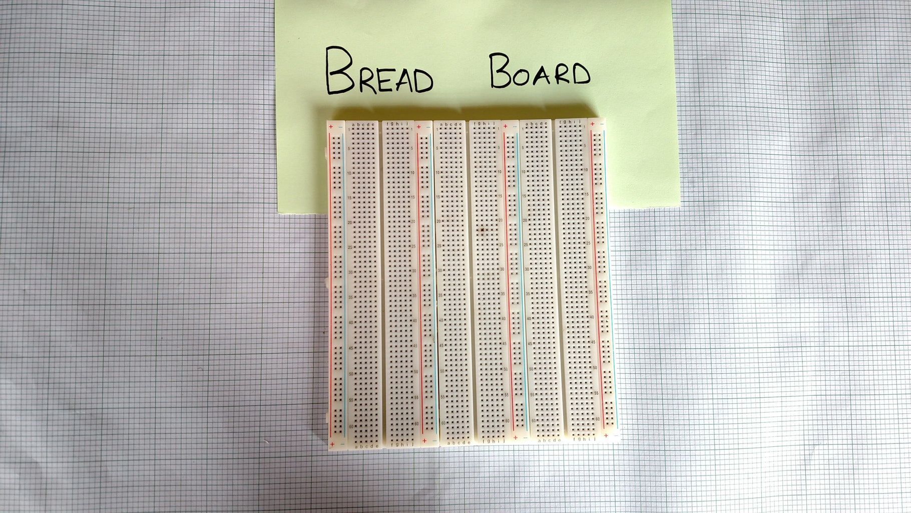

A breadboard is a widely used tool to design and test circuit. You do not need to solder wires and components to make a circuit while using a bread board. It is easier to mount components & reuse them. Since, components are not soldered you can change your circuit design at any point without any hassle. It consist of an array of conductive metal clips encased in a box made of white ABS plastic, where each clip is insulated with another clips. There are a number of holes on the plastic box, arranged in a particular fashion. A typical bread board layout consists of two types of region also called strips. Bus strips and socket strips. Bus strips are usually used to provide power supply to the circuit. It consists of two columns, one for power voltage and other for ground.
https://en.wikipedia.org/wiki/Breadboard
Step 13: Multimeters


A multimeter is a handy tool that you use to measure electricity, just like you would use a ruler to measure distance, a stopwatch to measure time, or a scale to measure weight. The neat thing about a multimeter is that unlike a ruler, watch, or scale, it can measure different things — kind of like a multi-tool. Most multimeters have a knob on the front that lets you select what you want to measure. Below is a picture of a typical multimeter. There are many different multimeter models; visit the multimeter gallery for labeled pictures of additional models.
Step 14: Arduino
Arduino is an open-source platform used for building electronics projects. Arduino consists of both a physical programmable circuit board (often referred to as a microcontroller) and a piece of software, or IDE (Integrated Development Environment) that runs on your computer, used to write and upload computer code to the physical board.
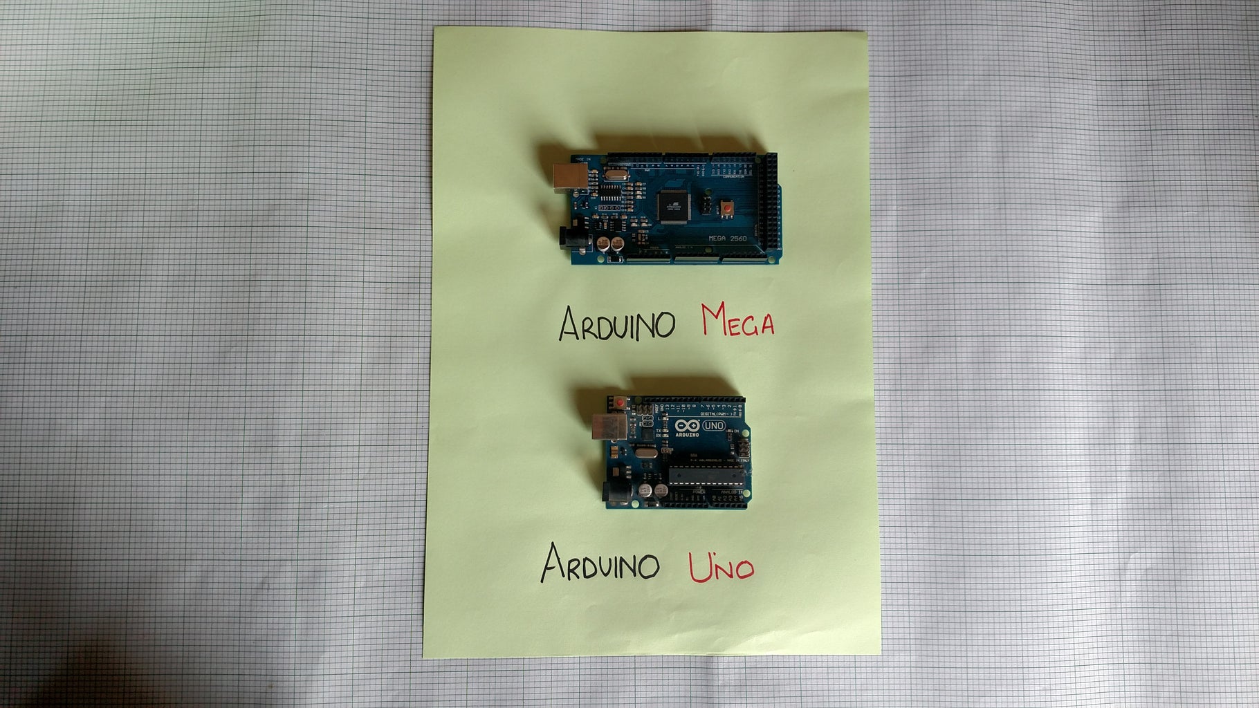
The Arduino platform has become quite popular with people just starting out with electronics, and for good reason. Unlike most previous programmable circuit boards, the Arduino does not need a separate piece of hardware (called a programmer) in order to load new code onto the board – you can simply use a USB cable. Additionally, the Arduino IDE uses a simplified version of C++, making it easier to learn to program. Finally, Arduino provides a standard form factor that breaks out the functions of the micro-controller into a more accessible package.
Step 15: Autodesk 123D


When you’re getting started in the world of Arduino, wiring up a simple project and figuring out how to code it is the best way to learn. But if you don’t have access to an Arduino, want a faster way to mock up a circuit, or just want to try something new, 123D Circuits is a great way to give it a go online.
123D Circuits lets you create and test virtual Arduino circuits, check your wiring, debug your code, and experiment with different setups. It’s a fantastic tool for anyone getting into Arduino for the first time or experts who want some flexibility in how they prototype and test.
www.circuits.io
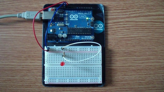
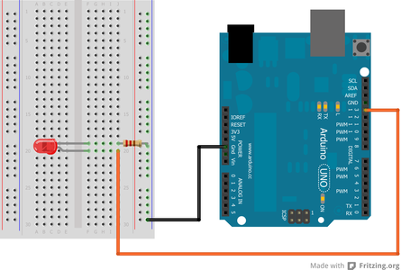
Step 16: Making a Simple Arduino Circuit
Materials Required:
- 1 x LED
- Jumper Cables
- 330 Ω Resistor1 x
- Arduino UNO board
- USB cable
- Computer with Arduino software installed
- Breadboard
Make the connections as follows:
LED (Anode) - D3
LED (Cathode) - Resistor 330 ohm
Resistor - GND
Load the following code:
/*
SparkFun Inventor's Kit Example sketch 01
BLINKING A LED
Turn an LED on for one second, off for one second, and repeat forever.
Hardware connections:
Most Arduinos already have an LED and resistor connected to pin 13, so you may not need any additional circuitry.
But if you'd like to connect a second LED to pin 13, or use a different pin, follow these steps:
Connect the positive side of your LED (longer leg) to Arduino digital pin 13 (or another digital pin, don't forget to change the code to match).
Connect the negative side of your LED (shorter leg) to a 330 Ohm resistor (orange-orange-brown). Connect the other side of the resistor to ground.
pin 13 _____ + LED - _____ 330 Ohm _____ GND
(We always use resistors between the Arduino and and LEDs to keep the LEDs from burning out due to too much current.)
This sketch was written by SparkFun Electronics, with lots of help from the Arduino community. This code is completely free for any use. Visit http://learn.sparkfun.com/products/2 for SIK information. Visit http://www.arduino.cc to learn about the Arduino.
Version 2.0 6/2012 MDG *
/ Welcome to Arduino!
// If you're brand-new to this, there will be some new things to // learn, but we'll jump right in and explain things as we go.
// The Arduino is a tiny computer that runs programs called // "sketches". These are text files written using instructions // the computer understances. You're reading a sketch right now.
// Sketches have computer code in them, but also (hopefully) // "comments" that explain what the code does. Comments and code // will have different colors in the editor so you can tell them // apart.
// This is a comment - anything on a line after "//" is ignored // by the computer.
/* This is also a comment - this one can be multi-line, but it must start and end with these characters *
/ A "function" is a named block of code, that performs a specific, // well, function. Many useful functions are already built-in to // the Arduino; others you'll name and write yourself for your // own purposes.
// All Arduino sketches MUST have two specific functions, named // "setup()" and "loop()". The Arduino runs these functions // automatically when it starts up or if you press the reset // button. You'll typically fill these function "shells" with your // own code. Let's get started!
// The setup() function runs once when the sketch starts. // You'll use it for things you need to do first, or only once:
void setup() { // The Arduino has 13 digital input/output pins. These pins // can be configured as either inputs or outputs. We set this // up with a built-in function called pinMode().
// The pinMode() function takes two values, which you type in // the parenthesis after the function name. The first value is // a pin number, the second value is the word INPUT or OUTPUT.
// Here we'll set up pin 13 (the one connected to a LED) to be // an output. We're doing this because we need to send voltage // "out" of the Arduino to the LED.
pinMode(13, OUTPUT);
// By the way, the Arduino offers many useful built-in functions // like this one. You can find information on all of them at the // Arduino website: http://arduino.cc/en/Reference }
// After setup() finishes, the loop() function runs over and over // again, forever (or until you turn off or reset the Arduino). // This is usually where the bulk of your program lives:
void loop() { // The 13 digital pins on your Arduino are great at inputting // and outputting on/off, or "digital" signals. These signals // will always be either 5 Volts (which we call "HIGH"), or // 0 Volts (which we call "LOW").
// Because we have an LED connected to pin 13, if we make that // output HIGH, the LED will get voltage and light up. If we make // that output LOW, the LED will have no voltage and turn off.
// digitalWrite() is the built-in function we use to make an // output pin HIGH or LOW. It takes two values; a pin number, // followed by the word HIGH or LOW:
digitalWrite(13, HIGH); // Turn on the LED
// delay() is a function that pauses for a given amount of time. // It takes one value, the amount of time to wait, measured in // milliseconds. There are 1000 milliseconds in a second, so if // you delay(1000), it will pause for exactly one second:
delay(1000); // Wait for one second
digitalWrite(13, LOW); // Turn off the LED
delay(1000); // Wait for one second
// All together, the above code turns the LED on, waits one // second, turns it off, and waits another second.
// When the computer gets to the end of the loop() function, // it starts loop() over again. So this program will continue // blinking the LED on and off!
// Try changing the 1000 in the above delay() functions to // different numbers and see how it affects the timing. Smaller // values will make the loop run faster. (Why?) }

Participated in the
Circuits Contest 2016


