

Introduction: How to Burn Arduino Bootloader W/ Magnolia Board (Cost and Size of Pack of Gum KickStarter)


Annika O'Brien created a KickStarter project here: https://www.kickstarter.com/projects/annikaskywalker/microprocessor-about-the-cost-and-size-of-a-pack-o
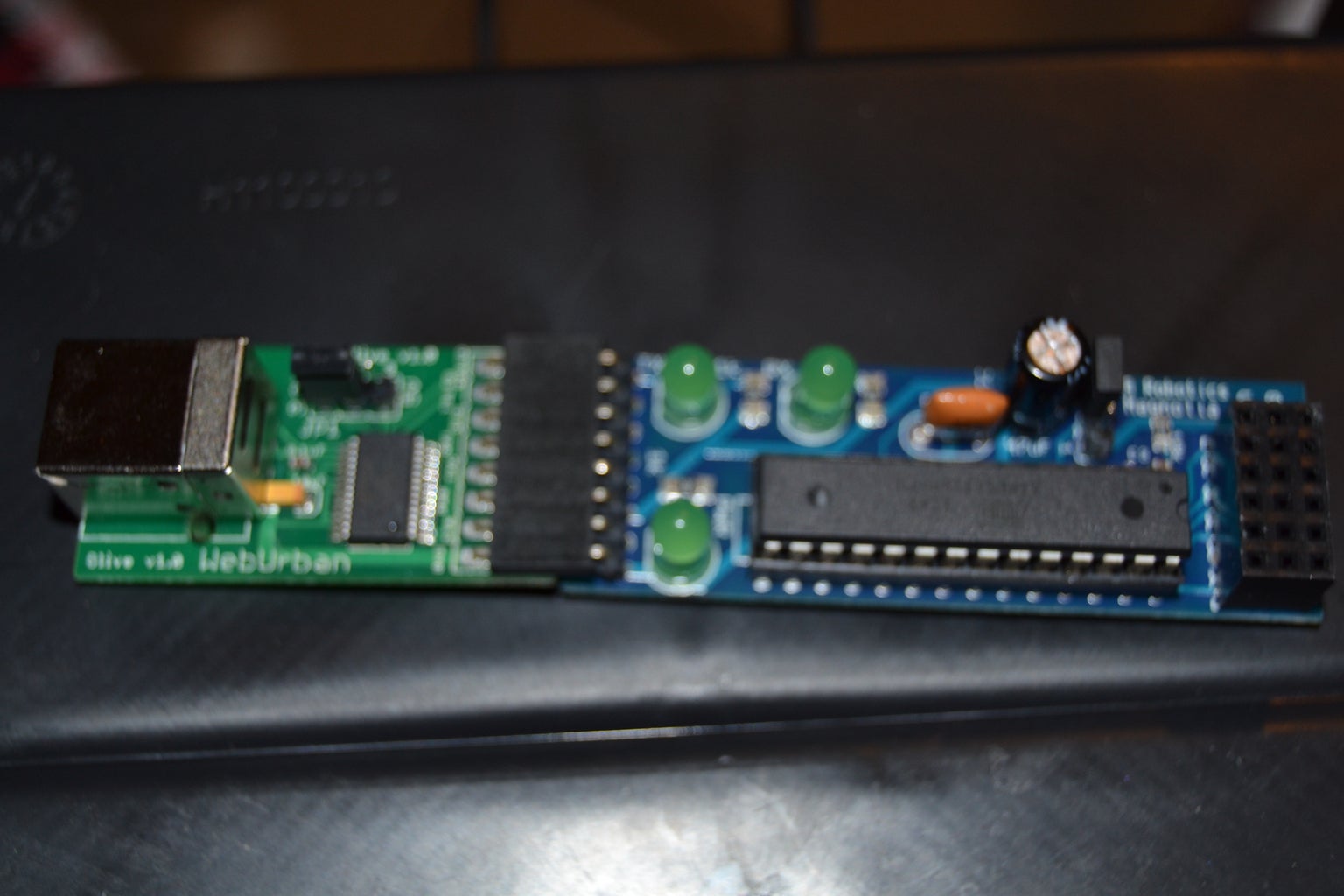
The Magnolia is a fun little board, very similar to an Arduino. In fact, it's compatible with the Arduino IDE. The only downside to its size are the limited number of broken-out pins. There's 6 analogue pins, each with a VCC & GND.
Paired with "Olive" (the USB FTDI board, you can connect it to your computer with a USB A to B cable.
It's great to mount on your project, and swap out the ATMega328 chips, instead of the entire board. However, if you buy the Atmel chips without the Arduino bootloader already burned on it, you can't just plug it in and upload sketches.
It's no problem to use a regular Arduino Uno to burn the bootloader to a chip on the breadboard, but on the Magnolia you don't have the necessary breakout pins.
Don't worry, if you're patient, you can burn the bootloader with Magnolia, itself! It's just tedious. It took me a while to figure it out, as I had no guide to go by. However, you should have no problem if you follow these steps.
Step 1: Break Pins Out to Breadboard


Since Magnolia doesn't have break-out pin headers, you have to innovate your own.
First, take the ATmega328 with the bootloader, place it on the bread board, with the semi circle on the right. (Also be sure that the sides of the IC are on separate parts of the bread board, or they will short out. -Mine separates down the middle.)
Take the ATmega328 that you want to burn the boot-loader to, and place it about 5 holes away, with the semi circle on the left. The half-circles should be facing each other.
Caution: when connecting these pins, make sure you unplug the USB cord from Olive or your computer. Don't want to accidentally short the pins. It should be OK otherwise, but better safe than sorry.
Here's a good diagram that shows the pin numbers, if you don't know them.
The pin numbers I give you are how the pins are labeled on the processor, not how they are labeled on the arduino nor the breadboard. If you don't know how the pins are numbered, check the link above.
Now you need to connect the IC on the left to the Magnolia. Take some jumper wire and connect pins 1,2,3,4 & 7,8,9,10 from the IC socket to the IC. Note: the jumper wires don't fit great into the IC socket, but it's doable. I used some needle-nose pliers to nudge them in.
Connect the '+' rail to VCC and the '-' to Ground. Jumper it to the other side, as shown.
Connect '+' (VCC) to either 20 or 21. Then Short/jumper them together.
Connect '-' (Ground) to pin 22.
Step 2: Test Connections & Upload Arduino ISP


Now, time to test your connections.
Open Arduino IDE. I borrowed the image above from google, it isn't the most up-to-date IDE, make sure you get the latest. (1.05, I think)
Go to Tools>Board>Duemilanove w/ ATmega328
Also select the correct Serial Port, mine is COM 13.
Go to File>Examples>ArduinoISP
Upload the sketch.
You should get a nice "Upload Complete." when finished, but....
If you have an errors here:
Try disconnecting and reconnecting USB cord.
Make sure you've selected the right board and serial port.
Double check all connections.
Step 3: Connect Power Rails to IC on the Right.

Connect the positive rail to pins 7 & 20.
Connect the negative rail to pins 8 & 22.
Step 4: Start Connecting the Two IC's


If I say connect pin 'X' to pin 'Y', pin 'X' is from the IC on the left and pin 'Y' is from the IC on the right.
Connect pin 16 to pin 1.
Connect pin 17 to pin 17.
Connect pin 18 to pin 18.
Connect pin 19 to pin 19. - I had to break pin 19 (left) away from the rest of the jumbled mess, and then connect that to pin 19 on the right.
Step 5: Arduino IDE Setup.
OK, before you burn the bootloader, you will have to add an Arduino IDE file. However, you will first have to determine which ATmega328 chip you are trying to burn. Most people have ATmega328p (pico-power), but I happen to have a few ATmega328 (non pico-power).
It should say on your chip: "ATmega328-PU" (nonpico) or "ATmega328P-PU" (pico). If you have the nonpico version, you will have a little extra set-up to do.
Go to File>Preferences. Find your sketchbook location.
Navigate to your Sketchbook Location, create the directory "hardware" (if you don't already have it). Under "hardware" create the sub-directory "breadboard" Then, download the attached "boards.txt" file I have provided, and save it in the "breadboard" folder.
If you are using the "ATmega328P-PU" (pico), you may continue to the next step of the instructable. If you have the nonpico, keep reading.
The "ATmega328-PU" (nonpico) & "ATmega328P-PU" (pico) are basically the same chip, and can be substituted in nearly any situation. However, they have different signatures, so the Arduino IDE doesn't know they are the same thing.
You will need to obtain Admin privileges.
Navigate to C:\Program Files (x86)\Arduino\hardware\tools\avr\etc\
rename "avrdude.conf" to "avrdude backup.conf"
Download the attached "avrdude.conf" and save it in the "C:\Program Files (x86)\Arduino\hardware\tools\avr\etc\" directory.
You should now be ready to continue.
Attachments

Step 6: More IDE Setup.
Go to Tools>Board and select "ATmega328p on a breadboard (8 MHz internal clock) " (or "ATmega328 on a breadboard (8 MHz internal clock)" if you're using the non pico.)
Go to Tools>Programmer>Arduino as ISP
Go to Tools>Burn Bootloader
This should work correctly. If you have any errors:
-Disconnect and reconnect the usb cord.
-Check your Board and Programmer settings are ok.
-Check all connections
-Disconnect and reconnect the usb cord.
-Restart Arduino IDE.
If nothing seems to work, your IC may have faulty fusebits. In which case, you are in deeper than this tutorial. However, this can happen if your chip has already had a bootloader on it, or if you aborted a bootloader attempt. Google "reset fuse bits parallel port" and look into building or buying yourself a High Voltage AVR programmer. Good luck!

Participated in the
123D Circuits Contest


