

Introduction: How to Construct a Device, That Securely Turns On/off Other Devices Via the Internet


IMPORTANT: READ THIS, before deciding to build something like this device. This device is connected directly to the mains power, which is potentially lethal to mess around with! I am not kidding you – the best scenario when subjected to electrical shock is that it hurts like h*ll, worst case scenario is that you DIE. You should not mess with mains power without a minimum of knowledge.
One of my good friends, Dan, is behind a new cool collaboration tool, Skarpline (https://www.skarpline.com). A bit like sharepoint, only much better! While drinking some beers, we discussed Skarpline, and Dan mentioned that he is planning to implement new functionality, where Skarpline can communicate with and control external systems. For demonstration purposes, Dan needed something to be controlled, “…and you’re good with hardware and stuff, so couldn’t you …”. Before long, the conversation turned towards Internet of Things, and how to communicate with IOT devices from an open platform, like Skarpline.
A nerd like me is a helpful being, so of course I grabbed the opportunity to add a new project to the ever-growing pile of unfinished projects, which takes up table space in my cellar-lab.
More beers and a brainstorm followed, as we started discussing what kind of device we wanted to control. We started with the usual coffee machine, but ended with a more generic device that can turn on/off two appliances via the Internet. One of the appliances could still be a coffee machine!
This is a small, but fun project, and I decided to take the opportunity to describe it to you. I suspect there are more people out there, who would like to make something similar. You can probably buy a commercial solution cheaper, but what’s the fun in that?
IOT is one of the popular buzzwords this year, and contrary to one of the other popular buzzwords, big-data, which also is part of the ongoing BS-bingo game, IOT is an area where the DIY people can have some fun making devices, what might even have a practical application at home.
This instructable will describe the project.
Step 1: Scope of the Project

Now let's make some fundamental choices, and establish the scope of the project.
Let me dazzle you with the most brilliant device, with a complexity that makes the cockpit of a Boeing Dreamliner look like the dashboard of Fred Flintstones car, and an industrial design so stunningly beautiful, that Apple will hire me on the spot…
Bzzzt (Steen enters ‘realism-mode’)
When you’re scoping a project, it will enhance the chances of success if you take into consideration the available resources:
- Number of developers available: 1 (And it’s been quite a few years since I last did full-time development)
- How many percent of my time can be dedicated this task: my sparetime
- Do you have any other tasks during your sparetime: Wife+child+house+volunteering+big garden+…
- Historic ability to finalize projects: Embarrassingly poor! My typical version of ‘done’ is a PCB with a bird’s nest of wires going in all directions. It might work, but it aint pretty!
Right… Lets start scoping the project by thinking about what we need.
Hardware: We’re going to make a device with two power plugs, which can be independently controlled via the Internet. Due to the limited time available I am going to settle for encapsulation with focus on protecting the user from electric shock (I have never tried being that ‘done’ with a DIY project before ☺), rather than making something pleasing to the eye (this have absolutely nothing to do with the fact, that I suck at the visual design. NOTHING, I say!)
So a trip to the local hardware store to get a couple of power plugs, a trip to the Internet to fins a suitable box to contain the electronics.
I have a lot of drawers in my cellar-lab, and one of these drawers revealed a couple of 230V/10A relays. I probably need to make a driver circuit for the relays but this can be done with a couple of transistors and diodes (drawer#2). So far, so good.
If I wanted to make a commercial product, the BOM cost and the physical size of the device would be of importance, but since I lack time and don’t really care too much about the cost per device, I opt for a standard platform, which in terms of power and features is totally overkill – but a HUGE timer-saver.
There are plenty of options to choose from, but I have selected the Raspberry Pi as my platform. Why? Because I found one in drawer#3.
A raspberry pi is a versatile small pcb containing a complete computer with Ethernet, USB and HDMI. A lot of people use them for cheap media centers, and I use a couple of rpi’s myself for my IHC project at home (might be subject for a later article series). The rpi is built around a 700 MHz ARM CPU and typically run a variant of Linux. You could install a limited version of win 10 as well, but I will stick with Linux.
The available I/O is more than adequate for our device with 17 GPIO (General Purpose I/O), where I only need two for the relays. I could choose to use the Ethernet port for Internet connectivity, but I prefer to install a wifi dongle since you can’t expect LAN to be available where the device will be placed.
By choosing Linux, you get the advantage that the full palette of tools in a normal linux distribution is readily available, making it much easier when we start coding.
Software: Since the device will be controlled by another software system, we must define an API (Application Programming Interface) such that the developer know how to send a command, and which results he can expect in return.
Next, since the device must be controlled via the Internet, a minimum of security must be in place, preventing bad guys from turning on your appliances.
A quick&dirty solution of implementing SSL and basic authentication will have to suffice. If it was to become a commercial product, significantly more thought must be put into making it a secure solution!
I choose to implement authentication ad standard http digest, which makes sure that the password is not sent in clear text. You could argue, that if using HTTPS further encryption of the password is not necessary. My reply would be https://xkcd.com/1354/.
The API can be realized by simply calling a webpage, where the command and parameters are part of the URL. The webpage then return a reply.
<a href="https://example.domain:8181/control.php?action=">https://example.domain:8181/control.php?action=</a><action>&device=<device></device></action>
Where ACTION can take following values (note: case sensitive):
ON 	: Turn on the device
OFF    	: Turn off the device
STATUS 	: Return if device is turned on or off
And DEVICE is the actual device that is queried. We implement two power outlets, so DEVICE can take the value 1 or 2
The return value could be e.g. DEVICE_1_ON or an error message.
The complete API document is available here: http://www.geekoholic.net/index.php/diy-iot-the-a...
From a software point of view, we need a webserver and it must use HTTPS. I choose as programming language to use PHP, simply because it’s the programming language for web servers I am accustomed to. There are few requirements for performance or language-specific features, so choose whatever language you want.
Scoping the project: If the device is to be installed and used by people without any IT-competencies we ought to consider how we can simplify the installation process.
We’re using wifi, so the basic installation steps will be: 1. Configure the SSID and WPA key to match the wifi router. 2. Configure the wifi router to reserve a specific IP address for the device 3. Configure a new NAT rule in the wifi router that points a specific port to the IP address of the device
This implies that you must access command line on the raspberry pi via ssh, and some basic knowledge on how to configure an internet router. No problem for the tech-savvy, but my mom would definitely have a hard time making it work. For a commercial solution a more streamlined and user-friendly installation process would have to be implemented. For our purpose, due to lack of time I choose to omit this work.
If anyone should have more time than me, I would suggest implementing WPS (Wifi-Protected Setup), so the wifi connection can be set-up by simply pressing a button on the device and the wifi router within 2 minutes. Secondly I would implement a basic UPnP functionality, enabling the device to create a NAT rule in the Internet router automagically.
Budget: With the decisions made, we can make an estimate on how much this is going to set us back moneywise. Since I already have parts in various drawers it will be cheaper for me, but if you would have to buy all the stuff
Note: I am merely estimating here. Actual cost highly dependent on your country, and your ability to shop around.
- Raspberry pi with SD card: $35
- Wifi USB dongle: $8
- 2 wall outlets: $30
- 2 relays: $15
- a piece of veroboard + various components: $20
- a suitable box: $10
Total, approximately $120 (way more expensive in Denmark - 25% V.A.T. anyone? ☹)
Is this expensive? Yes; a commercial version is available at half that price. But think about the hours of fun (and excitement from lethal danger) you get from playing with electronics, high-voltage and programming for a measly $60.
Secondly the beautiful thing with DIY is, that you can make exactly the functions that YOU need. I often bang my head against some frustrating limitation when messing with of-the-shelf products. For a DIY’er, if features are missing, just implement the missing features!
Finally by making your own device, you don’t share information about your behavior, as could be the case if using commercial solutions.
That’s it, folks. Next step is to get the missing parts, and start building the hardware.
Step 2: Preparing the Raspberry Pi


Last step was about specifying the gizmo that we’re going to build. Before we start making the hardware and software, the Raspberry Pi must be configured to suit our purpose. This step describe the configuration, and the next two steps will be about the hardware, and finally the software.
Warning: This step might be perceived as boring, but the stuff is a prerequisite for the subsequent teps, and I choose to describe the process in a sufficient detail-level to enable first-timers to have a real chance of implementing the device.
This instructable assume that we start with a Raspberry Pi with a fresh install of Raspbian. If you need help installing the OS on the Raspberry Pi, look here: https://www.raspberrypi.org/learning/noobs-instal...
There is a new version of Raspbian available, “Jessie”, and I have chosen the LITE version, since we’re not going to use the desktop for anything.
Do not connect the Raspberry Pi to any network until we have some basic security measures implemented. Instead connect a keyboard and a monitor, and power-up the device. Once boot is completed, login using “pi” as username and “raspberry” as password.
Le’s start by setting up some standard stuff:
sudo raspi-config

Choose ”Expand filesystem”, so we’re certain that the entire SD card is available for the filesystem.
Advanced options → Hostname I choose ”skarpline-iot”. Choose whatever suits you, but keep in mind that special characters are not supported.
Advanced options → SSH SSH must be enabled.
Advanced options → Memory Split Memory is shared between system and graphic adaptor. Since we’re not going to use grathics, leave as much as possible for the system, by choosing the lowest possible value (16).
Internationalisation Options → Change Timezone - Timezone: Copenhagen in my case.
Choose ’Finish’, and reboot the Raspberry Pi. Once booted, login as ’pi’ like before.
Now we must change the default username and password. This must be done before the Raspberry even smell an Internet connection.
The new user should enjoy the same rights as the old one, so let’s start by examining the groups that the user ‘pi’ is a member of:
pi@skarpline-iot:~ $ groups
pi adm dialout cdrom sudo audio video plugdev games users input netdev gpio i2c spi
Except ‘pi’ that will be deleted, we will assign these groups to our new user. Take the list, remove ‘pi’ and add commas between the names (no whitespaces). My new user is ‘rpi_admin’:
pi@skarpline-iot:~ $ sudo useradd -m -G adm,dialout,cdrom,sudo,audio,video,plugdev,games,users,input,netdev,gpio,i2c,spi rpi_admin
Now assign a password for the new user (and don’t use 1234. That’s mine!):
pi@skarpline-iot:~ $ sudo passwd rpi_admin
Enter new UNIX password:
Retype new UNIX password:
passwd: password updated successfully
Reboot the Raspberry Pi:
pi@skarpline-iot ~ $ sudo reboot
Login using the new username, and delete the ‘pi’ user:
rpi_admin@skarpline-iot ~ $ sudo deluser --remove-all-files pi
Now we can try connecting to our Raspberry Pi via a network connection. Connect the Raspberry Pi to your network using an Ethernet cable, and try connecting via SSH:
Once the cable is connected, verify that an IP address have been assigned to the Raspberry Pi:
rpi_admin@skarpline-iot ~ $ ifconfig
eth0      Link encap:Ethernet  HWaddr b8:27:eb:aa:d8:af
          inet addr:192.168.1.40  Bcast:192.168.1.255  Mask:255.255.255.0
          UP BROADCAST RUNNING MULTICAST  MTU:1500  Metric:1
          RX packets:1236 errors:0 dropped:0 overruns:0 frame:0
          TX packets:770 errors:0 dropped:0 overruns:0 carrier:0
          collisions:0 txqueuelen:1000
          RX bytes:165094 (161.2 KiB)  TX bytes:128214 (125.2 KiB)
My Raspberry Pi evidently have been assigned the IP address 192.168.1.40. If your device fail to connect to your LAN, you must debug the issue before proceeding. The remaining instructable assumes a working Internet connection.
Now that the Internet connection is up’n’running the keyboard and monitor can be disconnected. From now on it’s all happening via the SSH connection. On Linux or OSX open a termainal and type:
ssh rpi_admin@192.168.1.40
If you’re using Windows I recommend downloading Putty: http://www.chiark.greenend.org.uk/~sgtatham/putty...
Next we ensure, that all software on the Raspberry Pi is upgraded – This might take a while:
sudo apt-get update && sudo apt-get upgrade
IT security is much like a war, and as the general in the war must ensure that no flanks are open for attack, we must block any connections attempts to network ports that we do not intend to use. An open port is an invitation to attackers, which is why we install a firewall and create rules that block all ports, except 22/SSH, 80/HTTP and 443/HTTPS. Once SSL is working I recommend that we also block 80/HTTP. The firewall inside the Raspberry Pi is iptables, which is a nightmare to configure, and understand. Therefore let’s install UFW (Uncomplicated Firewall), providing an easy-to-use shell on top of iptables.
rpi_admin@skarpline-iot:~ $ sudo apt-get install ufw
To check if the firewall is correctly configured, I recommend using nmap. To verify the state of ports on the Raspberry Pi (Note: nmap must be run form a PC connected to the LAN. Nmap is a linux/OSX tool, but windows version is available here: https://nmap.org/book/inst-windows.html):
sudo nmap –sA 192.168.1.40
… All 1000 scanned ports on 192.168.1.40 are unfiltered …
All ports are open (= unfiltered), so let’s enable UFW and add the rules for ports 22, 80 and 443:
rpi_admin@skarpline-iot:~ $ sudo ufw enable
rpi_admin@skarpline-iot:~ $ sudo ufw allow 22/tcp
rpi_admin@skarpline-iot:~ $ sudo ufw allow 80/tcp
rpi_admin@skarpline-iot:~ $ sudo ufw allow 443/tcp
Retry the portscan:
sudo nmap –sA 192.168.1.40
Not shown: 997 filtered ports
PORT    STATE      SERVICE
22/tcp  unfiltered ssh
80/tcp  unfiltered http
443/tcp unfiltered https
Much better! Now all ports are closed (filtered), except 22, 80 and 443. One more security measure – Install fail2ban, protecting against unauthorized login attempts:
rpi_admin@skarpline-iot:sudo apt-get install fail2ban
Obviously we need a webserver, and php. I choose apache2 as webserver:
rpi_admin@skarpline-iot:~ $ sudo apt-get install apache2
rpi_admin@skarpline-iot:~ $ sudo apt-get install php5
Let’s see if the Raspberry Pi now is reachable on http. In a browser type http://192.168.1.40, where 192.168.1.40 is swapped with the IP address of your Raspberry Pi..
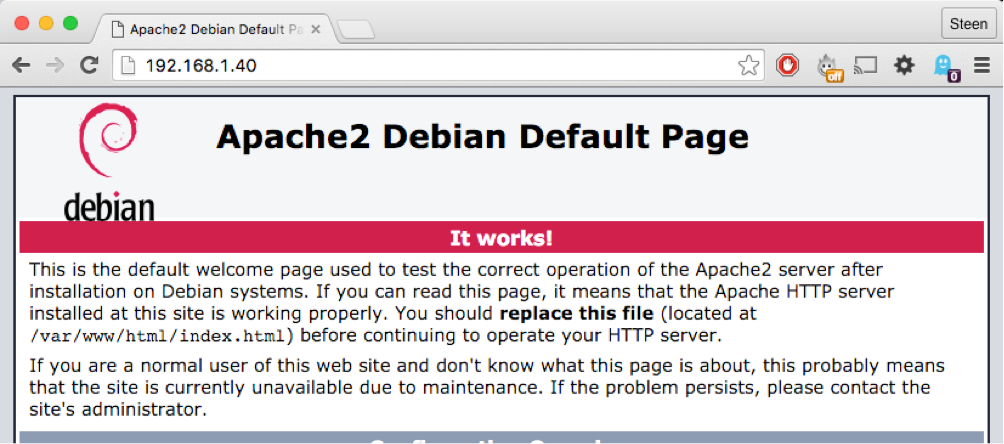
Beautiful!
Maybe php works as well?
Create a php-file in the web folder:
pi_admin@skarpline-iot:~ $ cd /var/www/html/
rpi_admin@skarpline-iot:/var/www/html $ sudo touch test.php
rpi_admin@skarpline-iot:/var/www/html $ sudo nano test.php
Write the small script below in the file test.php (save by typing ctrl+x)
<?php echo phpinfo(); ?>
Now type http://192.168.1.40/test.php
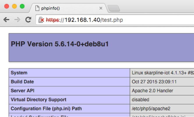
We’re getting there, but we’re not done yet. Now enable SSL:
rpi_admin@skarpline-iot:/var/www/html $ sudo a2enmod ssl
rpi_admin@skarpline-iot:/var/www/html $ sudo service apache2 restart
rpi_admin@skarpline-iot:/var/www/html $ sudo a2ensite default-ssl
Now type https://192.168.1.40/test.php

Fantastic – now we’re talking! If this were hardware, now would be the time to lift your hands and slowly step away from the table.
Why the warning in the browser? It’s merely the browser telling you, that the certificate is not an official certificate and therefore not trusted. You will always get this error when accessing an IP address, since the certificate is bound to the FQDN (Fully Qualified Domain Name) of the site. In our case even using the FQDN you’d still get the error, since we’re using a locally signed (self signed) certificate.
If you get this kind of warning when using net banking, I recommend that you stop what you’re doing!
I choose to don’t care, since for our purpose it’s fine. A commercial product is of course another matter. You can get free certificates many places, e.g. here: : https://www.sslshopper.com/article-free-ssl-certi...
We accept the risk in the browser, and are now able to access the webpage via HTTPS:
Last thing to configure is the wifi. First make sure that the wifi dongle is functioning correctly – it ought to work automagically when connected to USB.
rpi_admin@skarpline-iot:~ $ sudo iwlist wlan0 scan
wlan0     Scan completed :
…
Cell 03 - Address: 12:34:56:78:98:76
                    ESSID:"No_I_dont_want_to_share_my_ssid "
                    Protocol:IEEE 802.11bgn
                    Mode:Master
                    Frequency:2.472 GHz (Channel 13)
                    Encryption key:on
                    Bit Rates:144 Mb/s
                    Extra:rsn_ie=30140100000fac040100000fac040100000fac020c00
                    IE: IEEE 802.11i/WPA2 Version 1
                        Group Cipher : CCMP
                        Pairwise Ciphers (1) : CCMP
                        Authentication Suites (1) : PSK
                    IE: Unknown: DD8C0050F204104A0001101044000102103B0001031047001092C81F59E93B13E0061B4916F8D00DBE102100055A7958454C1023000C564D47383932342D423130411024000C564D47383932342D4231304110420007393633363847571054000800060050F20400011011000C564D47383932342D4231304110080002200C103C0001031049000600372A000120
                    Quality=48/100  Signal level=100/100
rpi_admin@skarpline-iot:~ $
Excellent, my wifi is detected. Now we configure the settings in the Raspberry Pi, which is done by editing the wpa_supplicant.conf file:
rpi_admin@skarpline-iot:~ $ sudo nano /etc/wpa_supplicant/wpa_supplicant.conf
And add the wifi ssid and wpa key to the file (Your ssid/wpa key, not mine!):
network={
    ssid="No_I_dont_want_to_share_my_ssid_with_the_world"
    psk="No_I_definately_dont_want_to_share_my_wpa_key"
}
Reboot the Raspberry Pi, and remember to disconnect the LAN cable. After completing booting, the Raspberry Pi will now connect automatically to the wifi (it might take a minute or two).
Last thing, before you’re off the hook: We must install a suitable library for communicating with the GPIO pins of the Raspberry Pi. I choose wiringPi, which must be installed from github. First install git:
rpi_admin@skarpline-iot: $ sudo apt-get install git-core
Next retrieve wiringPi:
rpi_admin@skarpline-iot:~ $ git clone git://git.drogon.net/wiringPi
Cloning into 'wiringPi'...
remote: Counting objects: 944, done.
remote: Compressing objects: 100% (770/770), done.
remote: Total 944 (delta 671), reused 217 (delta 142)
Receiving objects: 100% (944/944), 290.40 KiB | 306.00 KiB/s, done.
Resolving deltas: 100% (671/671), done.
Checking connectivity... done.
rpi_admin@skarpline-iot:~ $
Now install wiringPi:
rpi_admin@skarpline-iot:~ $ cd wiringPi/
rpi_admin@skarpline-iot:~/wiringPi $ ./build
Wonder if it works?
pi_admin@skarpline-iot:~/wiringPi $ gpio -v
gpio version: 2.31
Copyright (c) 2012-2015 Gordon Henderson
This is free software with ABSOLUTELY NO WARRANTY.
For details type: gpio -warranty
Awesome!
Now the preparations are complete. If you made it this far, well done. This part was a bit boring, I admit. But next step will be on creating the hardware. There is a good chance of electrical shocks and solder iron burns. Stay tuned…
Step 3: The Hardware
I have been shopping ingredients since last step, so now we’re going to bake a cake. The recipe is simple:
- Grab a pot and add the ingredients
- Add solder
- Add heat, and stir
- Add a few drops of blood, a minor burn, and a liberal amount of obscene words (here you really must allow the imagination to flourish!)
- Stir again
- Realize that it is not working as intended
- Stare angrily at the setup for a couple of hours (you might want to take a small detour to the last part of step#4), give up for now and go to bed.
- Fix the totally obvious error that you should have discovered after 5 nanoseconds of pondering.
- Try again
- If it still doesn’t work, go to step#7, and remember last part of step#4: consider increasing level of obscenity
- If it works, raise your hands, and step carefully away from the table.
Just kidding! The hardware for our gizmo is quite simple. The only electronics to be designed and constructed are the driver circuits for the two relays. I decide to position a couple of LEDs above the power outlets to indicate if they’re on or off. The driver circuits for the relays will drive these LEDs.
Why not connect the relays directly to the GPIO ports of the Raspberry Pi? The reason is, that a microprocessor is only able to supply a tiny amount of current – in the case of the Raspberry Pi, the GPIOs are able to source approximately 15-16 mA, and a typical relay require significantly higher current, in particular initially when the relay is just activated, and the coil is being energized.
A relay consist of a coil wound around a ferrite core, that create an electro magnet once a current is passed through the coil. The magnet attract a switch that closes the mains circuit.
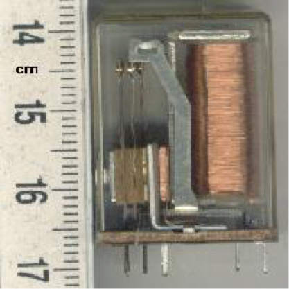
Source: Wikipedia
The relay I picked from the drawer require 6 V/60 mA, so there is definitely a need to boost the output from the Raspberry Pi GPIO pins. First of all the voltage level on the GPIO is 3.3V, and secondly we’re unable to source that amount of current. A small test reveal that the relay is perfectly able to operate on 5V instead of 6V, which is fortunate, since 5 V is readily available on the Raspberry Pi.
Luckily a driver circuit is really simple to design, using a standard NPB Bipolar Junction Transistor. A BC547 is perfectly suitable, since it can handle 0.5W without any cooling, and the relay will at the most draw 0.36W. We’ll use the transistor as a switch, and therefore we deliberately drive the transistor into saturation.
In short a transistor is a component with three terminals: Collector, Base and Emitter.
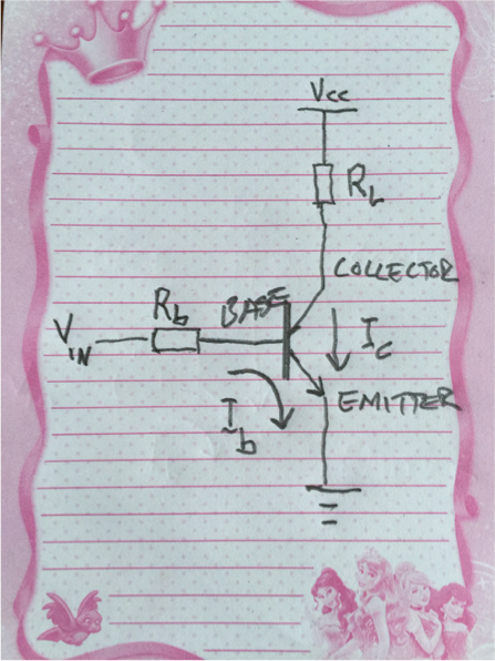
The clever thing about a transistor is, that a small current through base-emitter I_b can control a larger current through collector-emitter, I_c. The relation between I_b and I_c is called the gain, and for a BC547 it’s around 100. Therefore, if we need I_c to be 60 mA, we must pass at least 0.6 mA through I_b, and to make sure, let’s say 1.5 mA.
The base resistor R_b determine the current flowing through the base in accordance with Ohms law, U=R * I.
Output from the GPIO pin is 3.3V and the voltage drop across the base-emitter of a BC547 is around 900 mV, and hence the voltage across R_b will be 3.3-0.9=2.4V.
Thus we calculate the value of R_b as R_b = 2.4V /1.5mA = 1.6 kOhm. To allow for component tolerances, I select R_b = 1 kOhm.
Let’s have a look at the schematics of the circuit, which will be connected to the Raspberry Pi. As you can see, the schematic consist of two identical circuits, one for each relay to be controlled.

The base resistor, R2 is already described, but there are a few more things to explain, namely LED1/R1 and D1.
LED1 is the light emitting diode used to indicate if the power outlet is on, and R1 limits the current flowing through LED1 to approximately 18 mA. My LED's are really old and crappy. A modern LED type should work fine at significantly less current. If you feel the LED's are too bright, try experimenting with increasing the resistor value.
The purpose of D1 is to protect the transistor from the reverse polarity transient that occur from the relay. Electrically speaking a relay is a coil, and one of the basic properties of a coil is, that a magnetic field is created when a current is flowing through the coil. Once the current is cut off the magnetic field start breaking down causing the voltage across the coil to dramatically rise. The voltage will be in reverse polarity, and can be more than 100 times the original voltage. This phenomenon is utilized in the ignition coil in a car to create the spark across the terminals of the sparkplugs. In our case the spark could be inside the transistor, which is something to avoid! The diode is reverse biased to the power supply, and is therefore inert in the circuit during normal operation. Once a reverse polarity voltage occur across the diode it conducts, and allow the EMF from the coil to dissipate quietly. In this configuration the diode is typically called a flyback, clamp or suppressor diode.
Now the hardware is described. If we were to make a commercial product the next step would be to design the layout of the PCB, but since this is a one-off project with very simple hardware I just implement the circuits on a piece of veroboard.
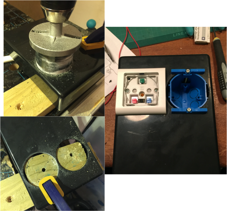
On my shopping spree I stumbled over a box for only $4 – a bargain! – and next step is to shoehorn all the stuff into this box, that admittedly is a teenyweeny bit too small. But $4! I had to have it! I take special precaution to isolate and fixate all wires and connections relating to the mains power in order to minimize the risk of electrical shock, short circuits and fire.
First thing is to decide where to put the electrical outlets on the front plate. I choose a location near the top of the box to maximize the available room inside the box for the electronic parts:
Now we can start fiddling wit all the parts to see how to best fit them inside the box. Primary, sizeable, components are: - The Raspberry Pi itself - The PCB with relay drivers - The two relays - A power supply for the Raspberry Pi
Let try to make an overview of the combined system to plan how to connect all the subsystems:

The power supply for the Raspberry Pi is a standard USB power supply used for e.g. smartphones and tablets. The one I found in the drawer is fairly small, and it is possible to solder the mains wires directly to the PSU (saves space).
After a fair amount of fiddling I were nearing the conclusion, that I had bought a too small box, but then I got stubborn: Come hell or high water, it MUST fit! The problem was that the Raspberry Pi was too long to fit crosswise, but only because the micro USB plug from the power supply was too long. A solution could be to try and find a connector with a 90 angle, but it was late and buying stuff is not in the spirit of a true DIY’er. So I grabbed a pair of pliers, and cut off the damn connector, then soldered the wire directly to the Raspberry Pi. There are a number of suitable places to do this – I chose to solder the wires across C6 (the large capacitor next to the USB connector.

Now all the bits and pieces are mounted and connected. As said earlier, the most important thing is to take special care to ensure that no wires or connections carrying mains power are exposed to the touch.
Notice: I have mounted an Ethernet connector on the side of the box. This is necessary to setup the wifi, unless you want to take the box apart before installation.
This concludes the part on creating the hardware. I hope you enjoyed reading. I survived the process without getting electrocuted and only with minor burns and a slightly sore throat from all the swearing.
But does it work? Does the box look okay from outside, and what idiot forgot that he was holding the front part of the box, when drilling holes for the Raspberry Pi mount?
Read the next step, where the software is written and the completed device demonstrated.
Step 4: The Software
In the past three steps we have specified the requirements for the device. We have made some choices and prepared the Raspberry Pi for the context that we will need, and last step was about creating the hardware. Most important of all, I survived so far! No electrocutions, and software frustrations have not been severe enough to make me jump out the window. Success!
This forth and final step will be on creating the software that implement the IOT functionality, and the demonstration of the finalised ‘product’.
But the first thing to do is deal with the cliff-hanger from last article, and show the final product. This is the gizmo in all it’s glory:

Not the most sexy design, but hey! I am an engineer, and as such much more interested in functionality, than design. The most important requirement on the physical design is to prevent me from dying from electrical shock, and I’m alive, so job well done!
But how about those weird holes in the front plate? Well. Cough-cough… Those holes are a perfect textbook example of the consequences on being in a hurry and not thinking your actions through. It was on the wrong side of 11pm a Wednesday night, and I had set up a goal that I had to be done with mounting the Raspberry Pi in the box before going to bed. While trying a lot of different combinations, I found the optimal position, and thought “Yes!”, grabbed the power drill and drilled a couple of holes for the mounting screws. Then I realized what I’d done, and jumped directly to let last part of item#4 in the hardware step (swearing):
Luckily the damage is manageable, since I anyway planned to cover the lower part of the device with a small ‘commercial’:
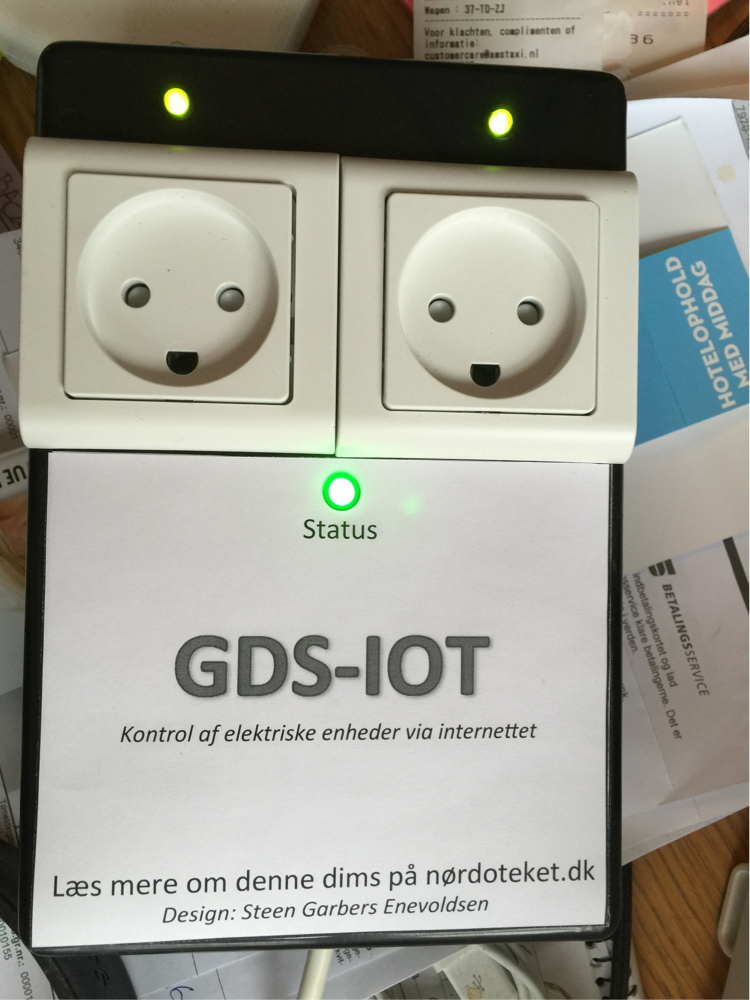
Now let’s do some coding! The first thing is to create the script that controls the status LED. The LED is a RGB type, so we can signal all sorts of different events (system ok, but no wifi, wrong wpa key, internal temperature too high, etc.), but I choose in this first version to make do with green = system ok, and wifi connected and red = no network connection. The script is written in python, and the complete source code can be found here: http://www.geekoholic.net/index.php/157-2/
The script determines the default gateway of the network, which typically correspond to the IP address of the router, and attempt to ping this IP address. The happen in an infinite loop, and depending on the reply to the ping, the LED is set as green/red. Python is a easy language to code, and I use the RPi.GPIO library to control the GPIO pins. The LED is connected to GPIO#9, 10 and 11(green, blue, red), and the GPIO pins must first be configured as either input or output:
GPIO.setmode(GPIO.BCM) # Use Broadcom pin numbers
GPIO.setup(9, GPIO.OUT) # Green LED, set as output
And you ”turn on” a pin, by setting it HIGH:
GPIO.output(9, GPIO.HIGH) # LED on
GPIO.output(9, GPIO.LOW) # LED off
The primary loop, where the ICMP echo requests are sent looks like this:
while True: # infinite loop
    response = os.system("ping -c 1 " + hostname) # send one ICMP packet to host
    if response == 0: # Reply
        # Network is reachable, LED=Green
        GPIO.output(11, GPIO.LOW)
        GPIO.output(9, GPIO.HIGH)
    else: # No reply
        # Network is NOT reachable, LED=Red
        GPIO.output(11, GPIO.HIGH)
        GPIO.output(9, GPIO.LOW)
This script must run on system boot, so we need to modify rc.local:
rpi_admin@skarpline-iot:~ $ sudo nano /etc/rc.local
Add ” /home/rpi_admin/status.py > /dev/null” to the file, and remember to change the directory to fit where you put the script on your system. The new rc.local file should look like this:
#!/bin/sh -e
#
# rc.local
#
# This script is executed at the end of each multiuser runlevel.
# Make sure that the script will "exit 0" on success or any other
# value on error.
#
# In order to enable or disable this script just change the execution
# bits.
#
# By default this script does nothing.

/home/rpi_admin/status.py > /dev/null

# Print the IP address
_IP=$(hostname -I) || true
if [ "$_IP" ]; then
  printf "My IP address is %s\n" "$_IP"
fi

exit 0
There is a limitation in this method: Even if there is no Internet connection the LED would be green, since I am only pinging the default gateway. If an address on the Internet itself were chosen as target (e.g. Google DNS 8.8.8.8), the test would show actual Internet connectivity. Personally I refrain from doing this, since in my opinion it is not polite to create something that continuously generate traffic load on other peoples servers.
An obvious next step for the LED status script would be to add a warning for too high temperature. You could use the on-chip sensor on the Raspberry Pi:
rpi_admin@skarpline-iot:~ $ echo $(($(cat /sys/class/thermal/thermal_zone0/temp) / 1000))
46
Or if you want decimals
rpi_admin@skarpline-iot:~ $ echo $(cat /sys/class/thermal/thermal_zone0/temp) 1000 | awk '{ print $1/$2 }'
45.464
Now we move to the code that implements the API. The complete source code is available here: http://www.geekoholic.net/index.php/diy-iot-contr... , and the API here: http://www.geekoholic.net/index.php/diy-iot-contr...
The API is implemented as a webservice, and the first thing to do is to validate the user. This is done with HTTP Digest (RFC-2617), and therefore we begin by rejecting all requests our webserver that do not contain authentication information in the header. We reject by returning a “HTTP 401 / UNAUTHORIZED” header (https://httpstatuses.com/401), and add a unique value to the reply , called a nonce (a one-time term).
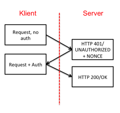
If we inspect the TCP traffic (Wireshark, if you haven’t tried it yet, please do. Fantastic tool!) the request/response look like this:

And in the code like this:
if (empty($_SERVER['PHP_AUTH_DIGEST'])) {
  header('HTTP/1.1 401 Unauthorized');
    header('WWW-Authenticate: Digest realm="'.$realm.
     '",qop="auth",nonce="'.uniqid().'",opaque="'.md5($realm).'"');

  die('UNAUTHORIZED');
  }
$_SERVER is a reserved variable in php containing all the information in the request that is received (http://php.net/manual/en/reserved.variables.server.php).
Nonce is generated with php’s uniqid() function which generates a unique string, based on the time of the request (if you’d send the same nonce every time, you’d be vulnerable to playback attacks).
So how does it look, when a header with correct authorization information is received? We get the desired response, and a HTTP 200 / OK header:
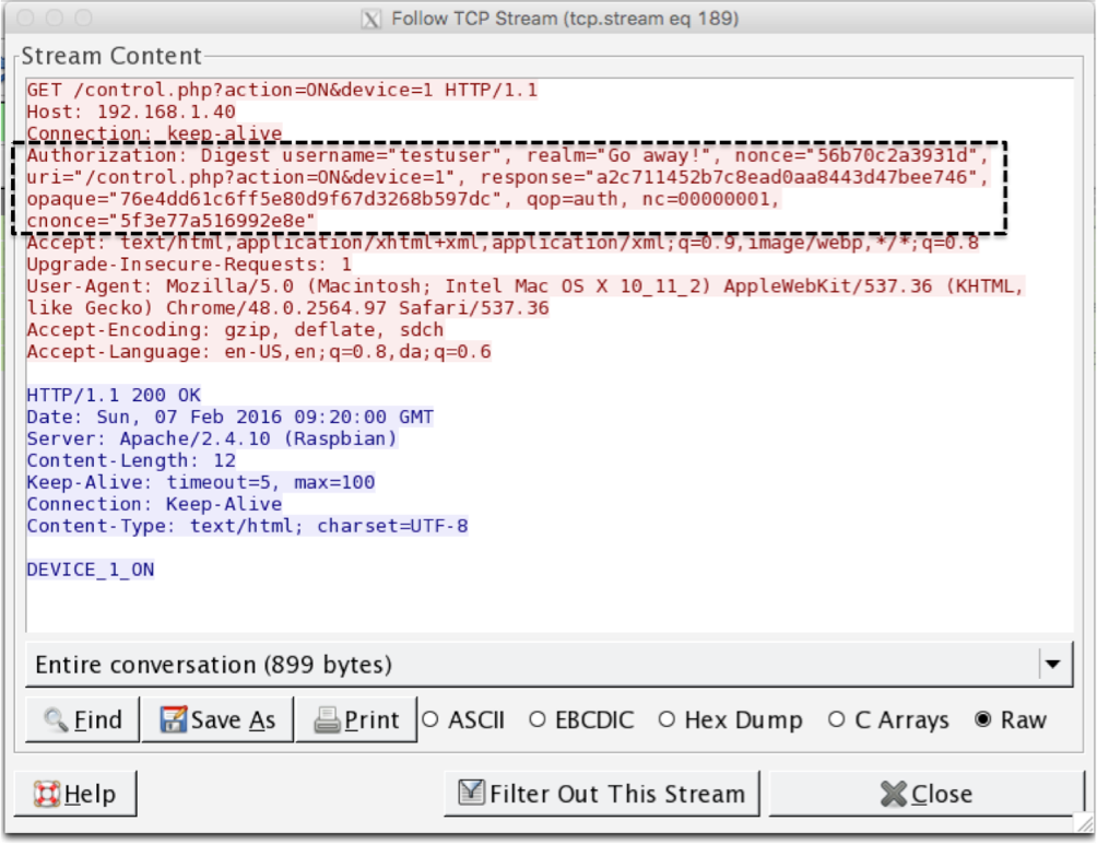
This reply contain some information that I will need to explain. First we must make sure, that the client deliveres all the necessary data in the header. This is done by parsing the PHP_AUTH_DIGEST variable:
// analyze the PHP_AUTH_DIGEST variable
if (!($data = http_digest_parse($_SERVER['PHP_AUTH_DIGEST'])) ||
    !isset($users[$data['username']]))
      die('WRONG_CREDENTIALS');
Next we calculate the response that we expect to receive, provided the client used correct username and password. HTTP Digest dictates, that this should be done by calculating a MD5 hash from the information, as described in RFC-2617 §3.2.2
// generate the valid response
$A1 = md5($data['username'] . ':' . $realm . ':' . $users[$data['username']]);
$A2 = md5($_SERVER['REQUEST_METHOD'].':'.$data['uri']);
$valid_response = md5($A1.':'.$data['nonce'].':'.$data['nc'].':'.$data['cnonce'].':'.$data['qop'].':'.$A2);
And finally, we compare the received response to the one we just calculated:
if ($data['response'] != $valid_response)
  die('WRONG_CREDENTIALS');
Now the user is validates, so let’s see what he asks us to do, according to the API. When you want to parse information in a “http/get”, you append “parameter=value” pairs to the URL. In php, these parameters are read by using the $_GET[‘parameter’]:
$action = $_GET['action'];
$port = $_GET['device'];
Device must be mapped to the correct GPIO port, and we must ensure that the request is for a valid device. This is done using a switch() statement:
switch ($port)
{
case 1:
    $portreal="27"; // Device#1 maps to GPIO#27
    break;
case 2:
    $portreal="17"; // Device#2 maps to GPIO#17
    break;
default:
    die('INVALID_DEVICE');
    break;
}
Finally! After all this soldering and coding, we have reached the point where we will perform the requested action. Again we use a switch() statement:
switch($action)
{
case ’ON’: // We want to turn on the device
  ..GPIO=HIGH
case ’OFF’: // We want to turn off the device
  ..GPIO = LOW
case ’STATUS’:
  ..Tell if the GPIO is HIGH or LOW
}
To manipulate the GPIO pins we use the library WiringPi, that we installes in part 2 of the series (link to part 2). WiringPi is a library for shell commands, so we need to breakout from PHP and make a system call. This is done with the shell_exec() command (where $portreal= 17 or 27):
$gpio_on = shell_exec("/usr/local/bin/gpio -g write " . $portreal . " 1"); // Turn on the desired GPIO
$gpio_stat = shell_exec("/usr/local/bin/gpio -g read " . $portreal); // Read status of port
This concludes the project. If you made this far, well done! I’m amazed how much I can write about so little, and still feel I only scratched the surface.
But we need a demonstration of the final product, or you’d just think it didn’t work!
A demo is not easy in writing, so I have created a small video for you.
As discussed in the first step of the Instructable, the electrical appliance of choice is a coffeemaker, but alas, my coffeemaker is a fancy machine that will need the press of a button after powering up, to make a cup of coffee.
How to deal with that problem? I don’t want to mess up my coffeemaker, but wait… An new project is forming inside my head… If I borrowed some of my daughters lego, and I know I have a finger lying around somewhere. Argh, stop! Enough writing:
Click here for a demonstration of the final product
All source code is released under revision 42 of the Beer-ware license.

Participated in the
IoT Builders Contest


