

Introduction: How to Flash or Program ESP8266 AT Firmware by Using ESP8266 Flasher and Programmer, IOT Wifi Module


Description:
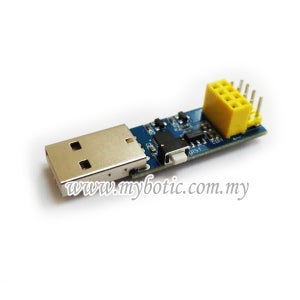
This Module is an USB adapter /programmer for ESP8266 modules of type ESP-01 or ESP-01S. It is conveniently fitted with a 2x4P 2.54mm female header to plug the ESP01. Also it breaks out all the pins of the ESP-01 via a 2x4P 2.54mm male header, so it is very convenient for user to debug the ESP8266.
The module is based on the USB-UART CP2104 which is compatible with all platforms. Onboard with the ESP8266 automatic download circuit. It is very convenient for users to download ESP-01/01S program, upgrade firmware, serial debugging and so on. It supports lots of software such as Arduino IDE, ESP8266 Flasher and Lexin FLASH_DOWNLOAD_TOOLS .
Specification:
- USB Type A interface.
- One 2x4P 2.54mm female header
- One 2x4P 2.54mm male header
- Operating Volatge: 3.3V
Step 1: List of Material


The attached photo shows the component needed In this tutorial:
- ESP8266 Flasher and Programmer
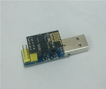
- ESP8266 Wifi Serial Transceiver Module
- Jumper wire.
Step 2: Hardware Installation
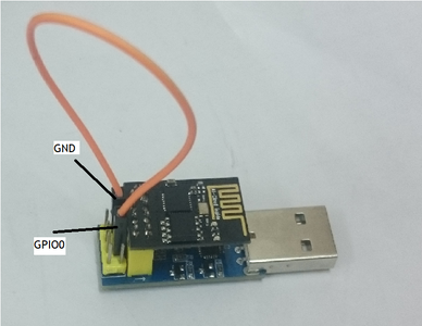
The photo above shows the connection between ESP8266 Flasher and Programmer and ESP8266 Wifi Serial Transceiver Module by using jumper wire.
Step 3: Download File
Download Driver for ESP8266 Flasher and Programmer
Download firmware inside the ESP8266 Flash Tool folder.
And Install the driver.
Attachments

Step 4: Firmware Installation

Window ( AT Firmware)
- After Download Firmware Flasher file. Extract it. Enter the folder, go to install_firmware > window.
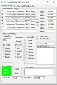
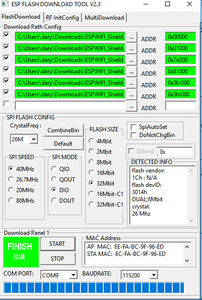
- Open ESP_DOWNLOAD_TOOL_V2.4.exe.
Choose the COM port ESP8266 Flasher and Programmer + ESP8266 Wifi Serial Transceiver module connecting to. Set the BAUDRATE to 115200.
Make sure ESP8266 Wifi Serial Transceiver module is in FLASH mode (Refer Step 2 first photo for hardware configuration)
Click START to install the firmware.
- bin\boot_v1.2.bin 0x00000
- bin\user1.4096.new.4.bin 0x01000
- bin\blank.bin 0x7e000
- bin\user2.4096.new.4.bin 0x81000
- bin\esp_init_data_default.bin 0x3fc000
- bin\blank.bin 0x3fe000
Step 5: AT Command in Arduino


- Disconnect jumper wire from ESP8266 Flasher and Programmer (Refer step 2 second photo)
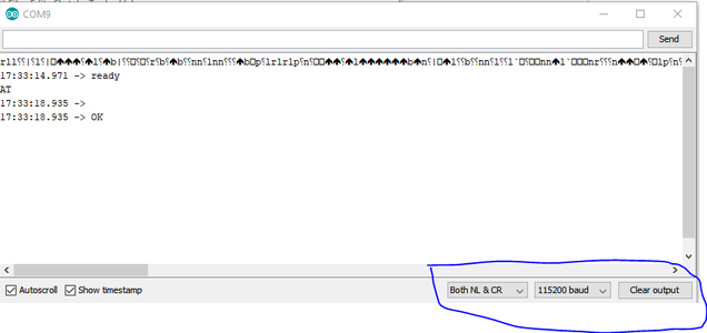
- Open your Arduino then click serial monitor.
- Press button Reset for make sure esp8266 is connected at serial monitor.
- Please follow the correct serial monitor configuration (Refer the photo above)
- Then write AT and send it, it will reply ok
- For more detail about AT Command, click this link for more information about AT Command
To change baudrate using AT Command:
AT+ UART_DEF=19200,8,1,0,0
For example 9600 baudrate / 8 data bits / 1 stop bits and none parity and flow control AT+UART_DEF=9600,8,1,0,0
the command AT+CIOBAUD=9600 it would change the baudrate temporarily


