

Introduction: How to Interface Arduino Board to PictoBlox: Scratch Based Programming Platform


Most of you must be familiar with Arduino Uno and how to program it using the conventional syntax-based programming language. Well, you might even be familiar with how complicated it can be to remember a number of lines just to make an LED blink. Well, that’s where Scratch comes into the picture, it is a graphical programming language that lets you write the entire code by just dragging and dropping the block instead of writing them. But there’s a teeny tiny problem, it’s almost impossible to control hardware using Scratch. This is where PictoBlox comes to the rescue. It is a Scratch 3.0 based programming software.
In this tutorial, we will briefly look over to the UI elements of Scratch, the two working modes, and finally, we will understand how to interface an Arduino Uno to PictoBlox, and perform a small activity to make the Uno’s Pin 13 LED blink.
You can download PictoBlox from here.
Let’s begin!
Step 1: Understanding the Basic Elements of the UI
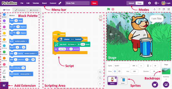
It has the following basic elements:
- Sprite
- Stage
- Block
- Script and the Scripting Area
Block: Block is the major element of all. You need to drag and drop the blocks in the scripting area. This simplifies or eliminates your need to worry about the syntax.
Script and the Scripting Area: The script is what you can call your program or code. Combination of different blocks systematically makes your script. The script is where you decide what will your script do. You need to write your script in the Scripting Area.
Step 2: Modes to Work In
Unlike Scratch, you can work in two modes in PictoBlox:
Stage Mode: Write scripts for the sprites and boards like Arduino Uno, Nano, Mega, and evive to interact with sprites in real-time. In case, if you disconnect the board in PictoBlox, you cannot interact anymore.
Upload Mode: Write scripts and upload it to the board that you have selected so that you can use the board even when it is not connected to your computer.
Step 3: Connecting Arduino to PictoBlox
Follow the procedure given below to interface Uno with PictoBlox.
Note: We are using Arduino Nano throughout the tutorial, you can use the Arduino Board of your choice. All you need to do is change the hat block.
- Connect Uno to your computer and open PictoBlox.
- Once you open PictoBlox, go to the toolbar and click on the Board menu. Select Arduino Uno.
In doing so, the Arduino Uno, Actuators, Sensors, Display, and Dabble extensions will automatically appear in the Block palette(on the left). If not, add them from the extension library by clicking on the purple-colored Add Extension button in the bottom-left corner of the window(whenever needed). - Next, click on the Connect menu and from the fly-out menu, select the Port to which Arduino Uno is connected e.g. COMXX or ttyXX. Once you select the port, the icon beside the Connect tab will become connected.

Step 4: Turing the Pin 13 LED ON and OFF
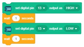
To turn the LED connected to pin 13 ON/OFF, we’re going to use the set digital pin () output as block.
On setting the output as HIGH, the LED glows and the LED turns OFF when the output is set as LOW.

Step 5: Making the LED Blink Once

Now to make the Pin 13 LED blink once, we are going to need to block of set digital pin () output as. Thus, duplicate it by right-clicking on it.
Once done, we need to make the LED ON for a second and then turn OFF, thus add the wait block below it and set the time as 1 second.
Finally, stack them together.
Step 6: Script to Make the LED Blink Forever
To make the process continuous, we’ll use the forever block from the Control palette. It helps to run the script till the time you stop the script.

To start any script, a hat block is necessary. As we will use the Upload Mode, drag and drop When Arduino Uno starts up block above the script.
Step 7: Uploading the Code
As we want the LED to blink even when the Arduino is not connected to PictoBlox, we will upload the code it to the board.
Thus, switch to Upload mode by toggling Upload button on the top right.
You'll notice that the Stage is replaced by an editor window. The editor window will contain the equivalent C++ program for the same script.
Now, to upload the code, click on the Upload Code button.
Step 8: Final Output

Once the upload is complete, the Pin 13 LED on the Arduino Uno board will start blinking.
Explore: Try changing the blinking speed of the LED.


