

Introduction: How to Make a Simple LED Circuit

This project will show you how to make a LED circuit on a breadboard.
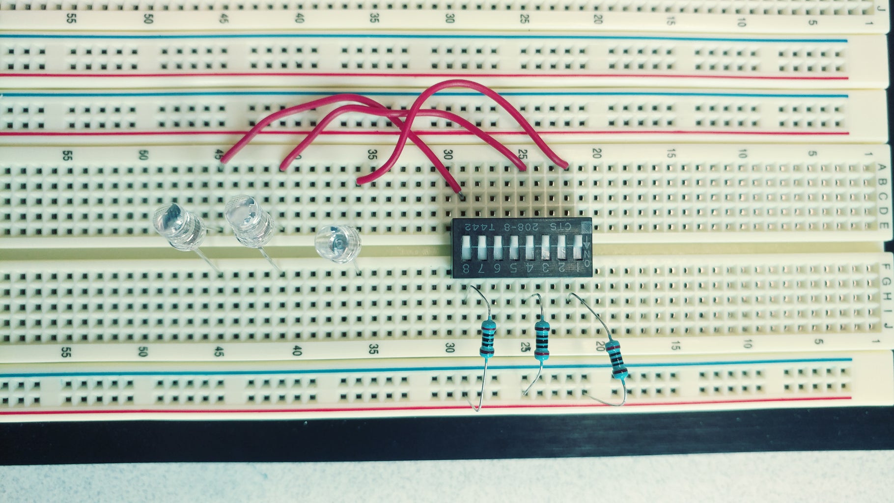
Materials
- Breadboard
- 6 Low Ohms resistors
- 3 LED lights
- 3 connecting wires
- 1 Switch Block
- 1 9V Battery
- 1 9V Battery connector
Reason to why this circuit is helpful. It shows that electrical circuits are a lot easier than people think. The user gets hand on experience on bread-boarding while showing them all of the basic parts that you need to run a circuit. When someone looks at a light switch, they never think about what is going on behind the switch, now they can learn a small scale version.
Step 1: Breadboards

About Breadboards
Breadboards have Holes all over, where wires can be inserted. The holes have metal on the inside, thus connecting wires to help complete the circuit.
In the center there are 10 holes horizontally. Each Hole is connected to other holes HORIZONTALLY and not vertically. There is a gap in the center that keeps each side disconnected from the other, This is usually where chips are placed, With both sides having open connections.
The Blue and Red lines are for power and ground, Red is power and Blue is Ground/Negative. Once connected, the Whole column from top to bottom will be live.
Step 2: Placing the Switch-Block

This block has 16 pins, (8 on each side) and should be placed on the center-line of the breadboard. Providing open connections along both sides of the switch. (The Block in this image has 8 switches total.)
Step 3: Placing First Resistors

All of the Resistors in this project are the same, you will be using 3 of them now.
- First, take one resistor and place stick one end of it in the RED line as shown in this photo.
- Go down a couple dots and repeat with the other resistors.
- Take the other end of the first resistor and place it next to PIN 1 on the switch block.
- Put resistor 2 next to pin 4.
- Place resistor 3 next to pin 8.
Step 4: LEDS

On the breadboard, go around 5-10 places below the switch block.
Begin to place each LED as shown.
- One pin on the left of the gap and another on the right side of the gap.
- Make sure to give each led some room from the others by placing each one a couple dots away.
(*Note that LED's have a positive and negative side to them, this is dictated by one of the LED pins being longer than the other. At the end of this project, If one or more of your LED's do not light up, try flipping the LED around.)
Step 5: Connecting the LEDs to the Switch Block

In this step you will us 3 wires to connect the LEDs to the Block.
- Start by placing each wire on the other side of the switch block from the resistors that we had placed earlier.
- Then run the wire and hook it next to one side of the LED
(This completes the connection from the switch to the LED)
Step 6: Connecting the LED to Ground

The circuit must be connected to ground, otherwise it will not be complete. In order to do this, we must have a resistor be the final connection from the LEDs to ground.
- Take each of the last three resistors and connect one side of them into the BLUE line (ground/negative).
- Connect the other end to the same line as the LED as shown in the photo above.
This Completes the circuit as it is now connected to a power and ground.
Step 7: Preparing the Power Supply

You will need the 9 Volt battery and the battery connector for this portion.
- The Battery has two connection terminals on top that should line up with the terminals on the wire connector.
- Connect the battery and the connector
- Make sure that the wire ends on the connector do not touch.
Step 8: Adding Power and Ground

- Take the two ends of the battery connector and place them as shown.\
- The BLACK wire connects to the RED line.
- The RED wire connects to the BLUE line.
Note: Once connected, the circuit is now live, so be careful.
*Make sure to disconnect the battery whenever working on the circuit.
Step 9: Turning on and Off the LEDs
Now that the circuit is live and fully connected, you can proceed to turn on and off the connected switches.
This will cause the corresponding LED to turn on and off when its switch is triggered.
Step 10: Changing and Disassembling
Disconnect the battery from the connector before changing anything on the circuit. This will make sure that no power is running through while you are making changes or while you are taking your project apart.


