

Introduction: How to Make a Smart Baby


It has three different inputs and three different outputs designed to engage, develop the mind, and be fun!
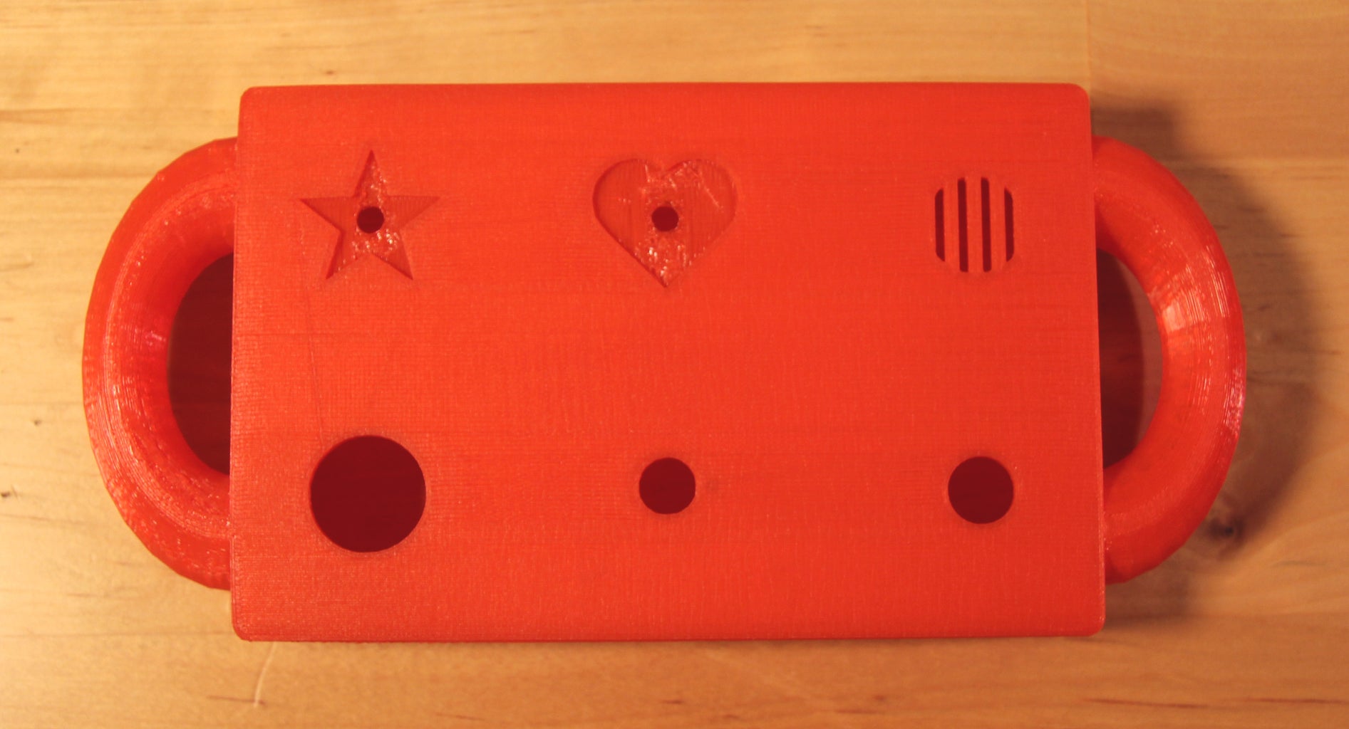
The first button turns on/off the LED in the star.
The round knob changes the brightness (PWM) of the LED in the heart.
The momentary button turns on a buzzer.
When the star LED and the buzzer are on at the same time the heart LED will turn red.
You can add more complexity if you'd like, but since my nephew is only 1 year old I thought I'd start off simple.
Step 1: Components and Tools

As many projects start, I found random parts that were laying around my room, and bought a couple additional things.
The parts are listed in the photo, but here are a few notes to help explain things:
I used an Arduino Duemilanove. You can use any Arduino as long as there are 7 digital (3 of them PWM), and 1 analog I/O ports.
The control knob I used fits the 1/4" shaft of the potentiometer. Make sure you buy a knob that has a set screw so that the baby can't easily pull it off the toy.
The resistors you need depend on what LEDs you use, what brightness you want, and desired buzzer loudness, etc. For the red 3mm LED (used for on/off status) I used a 390 ohm resistor. I used a 330 ohm resistor in the buzzer circuit so that the 'buzz' wouldn't be extremely loud. I used a 10k ohm resistor for the pushbutton switch and the rocker switch. For the yellow LED I used a 300 ohm resistor, and for the RGB LED I used 770 ohm resistors because the LED was super super bright.
I used 3 screws to attach the Arduino board to the case, 2 screws to attach the buzzer and 4 screws to attach the back plate. Screws work nicely because the threads are big and grab into the plastic case. Use whatever sizes fit your components.
Everything should be available for purchase at RadioShack, although they're also available at higher quality stores.
For tools you will need a soldering iron and 3D printer. If you don't have a 3D printer you can mount the switches into a box or send your file to a company that can print the case for you. You'll also need odds and ends like a screwdriver, wire cutters, solder...
Here are links to the parts I used:
Buzzer
Momentary pushbutton switch
Rocker switch
Control knob
3mm red LED
Arduino Duemilanove
RGB LED
Rotary potentiometer
Yellow LED 5mm
9v battery connector
Toggle switch
Resistors
Wire
Header
Heat shrink
Replicator 2 3D printer
Solder station
Step 2: Designing the Case


Designing the case of the toy.
I used a free browser-based 3D modeling tool called Tinkercad. I love Tinkercad because it is extremely easy to use, it can be used on any computer that is connected to the internet and it is capable of making complicated models almost as good as an expensive 3D modeling software could.
First I measured each of my components, modeled them in 3D, and then I built the case around the components. I made standoffs inside the case to hold up the buzzer and the arduino. On the front I made holes for the LEDs, switches, and knob to mount through, and I put some slits where the buzzer will go. On the top I made holes for the on/off switch and LED, and on the top and bottom I wrote my nephew's name. On each side I made a big handle for him to grab, and I rounded the corners of the main case so that it would feel smooth and friendly.
On the front I wanted to add some colorful shapes, so I added a star and heart around the two LEDs. My 3D printer only prints one color of material so I made each piece separately. I modeled a short recess into my case, slightly bigger than my shapes, and then I made a separate star and heart (with a hole to put the LED through).
After finishing the modeling I exported each as a .stl file.
*** I attached the .stl files for the 'smart baby toy' here for your use. What is a .stl file? Check out the wikipedia.
If you import the files into Tinkercad you can easily customize by putting your own kid's name on the sides.


Step 3: Print


Now we get to print!
I used a Replicator 2 printer. I took the .stl files, opened them in MakerWare (a free software used with MakerBots), and exported them into the .x3g file format. The Replicator 2 only reads .x3g files. I didn't change any of the export settings, and I did not use rafting or supports.
If you are using a different printer take the .stl files and print them however it says in your printer's documentation.
I printed each piece separately with 1.75mm PLA. For the star and heart I had to change the color of my filament between each printing.
If you look at the bottom two photos you'll see the back cover, and you may wonder why the two walls are curved. I actually printed them straight and curved them afterwards using my soldering iron. I ran the iron back and forth just enough to make the walls pliable, then I used my hands to curve them down. When the back cover is screwed onto the case those two walls line up behind the 9v battery. I curved them so that they would act like a spring and hold the battery in firmly.
Step 4: Attach the Inlay Shapes

The star and heart should just barely fit into their holes, but depending on your 3D printer they may be a little big.
You can use whatever tool is easiest for you to shave down the sides of the shapes. I like to use my soldering iron.
If your shapes fit very tightly then you're set. If not, you can use a little superglue to make sure the shapes don't fall out of the holes.
Step 5: Programming

Before putting the Arduino board in our toy we need to upload our software. If you haven't programmed an Arduino before you will need to download their free software. Also check out the Getting Started Guide.
Plug the Arduino into your computer.
Open the Arduino program and start a new sketch.
Cut and paste this code into your sketch:
int buttonPin = 7; // button is connected to pin 7
int ledPin = 3; // LED is connected to pin 3
int buttonStatus; // variable we'll use to store the button's status
int potPin = 3; // the potentiometer is connected to analog pin 3
int ledPin10 = 10; // RGB LED green connected to pin 10
int ledPin9 = 9; // RGB LED red connected to pin 9
int ledPin5 = 5; // RGB LED blue connected to pin 5
int val = 0; // variable to store the value coming from the sensor
int buttonMomStatus; // variable we'll use to store the momentary button's status
int momButton = 6; // momentary button is connected to pin 6
int buzzer = 8; // buzzer is connected to pin 8
void setup() {
Serial.begin(9600); // initialize serial communications at 9600 bps:
pinMode(buttonPin, INPUT); // Initialize the buttonPin as input
pinMode(ledPin, OUTPUT); // The LED is an output
pinMode(ledPin10, OUTPUT); // declare the ledPin10 as an OUTPUT
pinMode(ledPin9, OUTPUT); // declare the ledPin9 as an OUTPUT
pinMode(ledPin5, OUTPUT); // declare the ledPin5 as an OUTPUT
pinMode(momButton, INPUT); // Initialize the momButton as input
pinMode (buzzer, OUTPUT); //buzzer is output
}
void loop() {
buttonStatus = digitalRead(buttonPin);
if (buttonStatus == HIGH) {
digitalWrite(ledPin, HIGH); // If the button is pressed turn the LED on
}
else {
digitalWrite(ledPin, LOW); // Otherwise, turn the LED off
}
val = analogRead(potPin); // read the potentiometer value
analogWrite(ledPin10, val/4); // PWM the LED with the pot value (divided by 4 to fit in a byte)
analogWrite(ledPin9, val/4); // PWM the LED with the pot value (divided by 4 to fit in a byte)
analogWrite(ledPin5, val/4); // PWM the LED with the pot value (divided by 4 to fit in a byte)
delay(10); // wait 10 milliseconds before the next loop
buttonMomStatus = digitalRead(momButton);
if (buttonMomStatus == HIGH) {
digitalWrite(buzzer, HIGH); // If the momentary button is pressed turn the LED on
}
else {
digitalWrite(buzzer, LOW); // Otherwise, turn the LED off
}
//bonus section
if (buttonStatus == HIGH && buttonMomStatus == HIGH) { //if rocker and momentary switches are on at the same time
digitalWrite(ledPin10, LOW); // turn the ledPin off
digitalWrite(ledPin5, LOW); // turn the ledPin off, by turning them off the RGB LED turns red
delay(500);
}
}
Click the check mark to verify that this sketch works, then hit the arrow to upload it to your Arduino.
***You will need to have the correct board and COM port selected from the TOOLS menu. For any problems I suggest using the Arduino Troubleshooting page. It is quite useful.
I attached my Arduino code file for people who want to download that and import it into the Arduino program.
Attachments

Step 6: Testing the Circuit


I suggest testing your circuit before soldering it together. A breadboard makes this easy.
At this stage you will want to test different resistors to change the brightness of the 5mm LEDs and the loudness of the buzzer.
Here are the schematic and bread board drawings for my circuit.
Step 7: Solder


Next we get to place our parts into the case and solder them.
It is really important to mount the buttons in the case before doing any soldering to the Arduino because the buttons enter through the outside. Also don't forget that the nut will be screwed in from the inside, and the wires will have to pass through it.
1. Solder the toggle switch, 3mm LED, resistor, and 9v battery connector (check out the schematic). That will be our power circuit.
2. The ground and voltage out connect to the Arduino 'gnd' and 'Vin'.
3. Solder your wires and resistors onto your buttons, LEDs, buzzer and potentiometer (BTW, the LEDs are behind the Arduino).
4. The signal wire from each of them connect to the Arduino via a header strip.
5. Take the ground wire (black) from everything (LEDs, buzzer, buttons, potentiometer) and solder them together to a wire that goes to the second 'gnd' on the Arduino board.
6. Now take the power wire (red) from the two buttons and potentiometer, and solder them together to a wire that goes to the '3v3' on the Arduino board.
Every wire should be connected to something at this stage. If not, take a look back at the schematic.
Step 8: Final Assembly

Now that everything is soldered and programmed we can do the final assembly.
In case you haven't already done it, put the LEDs in their holes (put a dot of superglue on them if you prefer), place the Arduino board, screw it in to the standoffs, tighten the nuts on your buttons, potentiometer and toggle switch, screw in your buzzer, and plug in the 9v battery.
*If any components are slightly too big to fit in their hole use the soldering iron and gently apply heat to the hole, then place your component in.
Attach the back cover with 4 screws.
The assembly is complete!
Step 9: Play!


Turn it on and play!
The first button (rocker switch) turns ON the star LED.
The middle knob (potentiometer) changes the brightness of the middle LED.
The momentary button turns ON the buzzer.
When both buttons are ON the middle LED turns red!
*After testing I noticed that my middle LED was brighter than I preferred, so I printed a little dome to diffuse the light. I'm attaching a .stl file in case you want to print one too.
Attachments


Participated in the
Toy Contest

Participated in the
3D Printing Contest


