

Introduction: How to Make an Arduino Powered Mood Lamp

A Mood Lamp is a great beginner Arduino project!
This "Mood Lamp" project will show you how to create a lamp that changes colors when it's dark.
This just so happens to be a project from our Electronics curriculum but you can still create this project without being a member of Creation Crate!
Step 1: Hardware
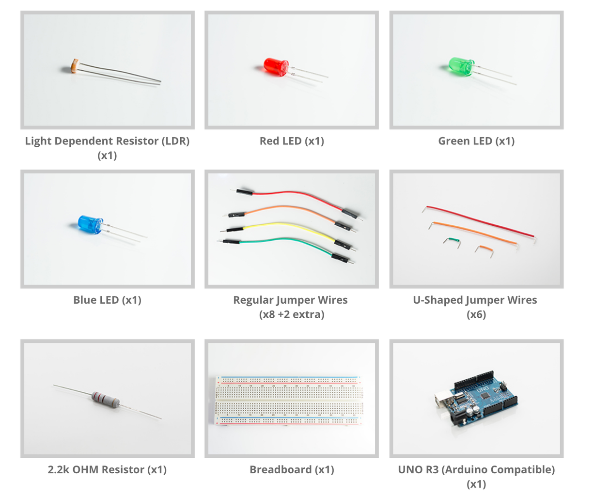
The Parts You Will Need:
Light Dependent Resistor (LDR) X1
UNO R3 (Arduino Compatible) X 1
Paper Lanter X 1
------------------------------------------------------------------------------------------
How to find these parts:
1. Google your way through life
2. Roll the dice with Amazon parts
3. Buy reliable parts from our Maker Shop
or
Receive every single part you need (with extra) in one crate with Creation Crate!
Step 2: LED and LDR

Step 3: Connect the Jumper Wires

Attach the U-shaped wires to the 6 locations shown.
Step 4: Connect the Uno Microcontroller

Attach the rest of the (8) wires as shown.
Step 5: Place the Lantern Over the LEDs

Step 6: Programming
1. Let's start by going to https://www.arduino.cc/en/Main/Software.
2. Download the Arduino Software (IDE).
3. Open the Arduino program and navigate to 'File > New'.
4. Delete all of the existing text/code. (Note: the program is made up of lines of code)
5. Navigate to 'File > Save' and save the program as "Mood Lamp".
6. Click next and start programming!
When you join Creation Crate, you receive access to an entire Online Classroom that breaks down each part of the code and teaches it to you step by step.
For time's sake, we will upload the entire code for you here.
------------------------------------------------------------------------------------------
/* Creation Crate Mood Lamp
This lamp smoothly cycles through a color spectrum. It only turns on when its surroundings are dark. Color equations (we’ll be using these later): Red = sin(x) Green = sin(x + PI/3) Blue = sin(x + 2PI/3) These equations are how the program will calculate the brightness of the LEDs.*/
// Step 1: Input User Defined Variables Think of variables like containers - they’re used to store information.
int pulseSpeed = 5; // This value controls how fast the mood lamp runs. You can replace this with any whole number.
int ldrPin = 0; // LDR in Analog Input 0 to read the surrounding light.
int redLed = 11; // red LED in Digital Pin 11.
int greenLed = 10; // green LED in Digital Pin 10.
int blueLed = 9; // blue LED in DIgital Pin 9. // These are the pins we are using with the UNO R3 (Arduino-compatible). You can see the numbers on the board itself.
int ambientLight; // This variable stores the value of the light in the room.
int power = 150; // This variable controls the brightness of the lamp (2-255).
float RGB[3]; // This is an ‘array’. It can hold 3 values: RGB[0], RGB[1], and RGB[2].We’ll use this to store the values of the Red, Blue, and Green LEDs.
float CommonMathVariable = 180/PI;
/* Step 2: Create Setup Loop This ‘loop’ is not really a loop. It runs once in the beginning to create the default values for our LEDs. */
void setup () {
Serial.begin(9600); // Starts the serial monitor, which can be used for troubleshooting.
// This tells the UNO R3 to send data out to the LEDs.
pinMode (redLed,OUTPUT);
pinMode (greenLed,OUTPUT);
pinMode (blueLed,OUTPUT);
// This sets all the outputs (LEDs) to low (as in off), so that they do not turn on during startup.
digitalWrite (redLed,LOW);
digitalWrite (greenLed,LOW);
digitalWrite (blueLed,LOW);
} // Opening brackets must be accompanied by closing brackets.
/* Step 3: Create Main Loop The previous sections are where we set up the variables. This section is where we put them to work! This part of the program is a ‘loop’. It repeats itself over and over again, making a small change in the brightness of the LEDs each time - this creates a smooth transition in colour. */
void loop () {
for (float x = 0; x < PI; x = x + 0.00001) {
RGB[0] = power * abs(sin(x * (CommonMathVariable))); // Red LED.
RGB[1] = power * abs(sin((x + PI/3) * (CommonMathVariable))); // Green LED.
RGB[2] = power * abs(sin((x + (2 * PI) / 3) * (CommonMathVariable))); // Blue LED.
ambientLight = analogRead(ldrPin); // This reads the light in the room and stores it as a number. Serial.println(ambientLight); // Prints the value to the serial monitor for troubleshooting
// This ‘if statement’ will make the lamp turn on only if it is dark. The darker it is, the higher the number.
if (ambientLight > 100) {
// These ‘analogWrite’ statements will send the values calculated above to the LEDs.
analogWrite (redLed,RGB[0]);
analogWrite (greenLed,RGB[1]);
analogWrite (blueLed,RGB[2]);
} // Don’t forget to close this ‘if statement’ with a bracket!
else {
// This ‘else statement’ will only activate if the ‘if statement’ above does not (ie. If it is too bright in the room). The LEDs will turn off.
digitalWrite (redLed,LOW);
digitalWrite (greenLed,LOW);
digitalWrite (blueLed,LOW); }
// This loop calculates the delay for each colour depending on its current brightness. Brighter LEDs will change colour slower and vice versa.
for (int i = 0; i < 3; i++) {
if (RGB[i] < 1) { delay (20 * pulseSpeed);
}
// ’else if’ means only one of these conditions can activate at a time.
else if (RGB[i] < 5) { delay (10 * pulseSpeed); }
else if (RGB[i] < 10) { delay (2 * pulseSpeed); }
else if (RGB[i] < 100) { delay (1 * pulseSpeed); }
else {} // This blank ‘else statement’ is a fail-safe mechanism. It instructs the program to do nothing if the conditions above do not activate. This prevents the program from generating errors when calculating delays.
}
delay(1);
}
}
Step 7: More Learning Resources
Join Creation Crate And Learn How To Build Electronic Projects Like A ...
- Bluetooth Boombox
- Line Following Roverbot
- Weather Station
- Alarm Clock
------------------------------------------------------------------------------------------
More Maker Resources
Subscribe To Our Youtube Channel
Receive Weekly Maker Emails With Project Ideas And Videos
------------------------------------------------------------------------------------------
Blogs You Might Enjoy


