

Introduction: How to Mount CC3D Flight Controller to Quadcopter (Assembly, Wiring, Software Configuration)


The CC3D may be the most popular flight controller in flight hobbyist circle due to its powerful performance and reasonable price. But how to mount it may be the greatest problem for a green hand. This article is to teach you how to mount a CC3D flight controller on a drone. Different drone may varies in structure. Happen to have a SFX190 frame at hand, we will take a SFX190 frame as an example.
Any question or advices are welcome.
Step 1: Prepare Components
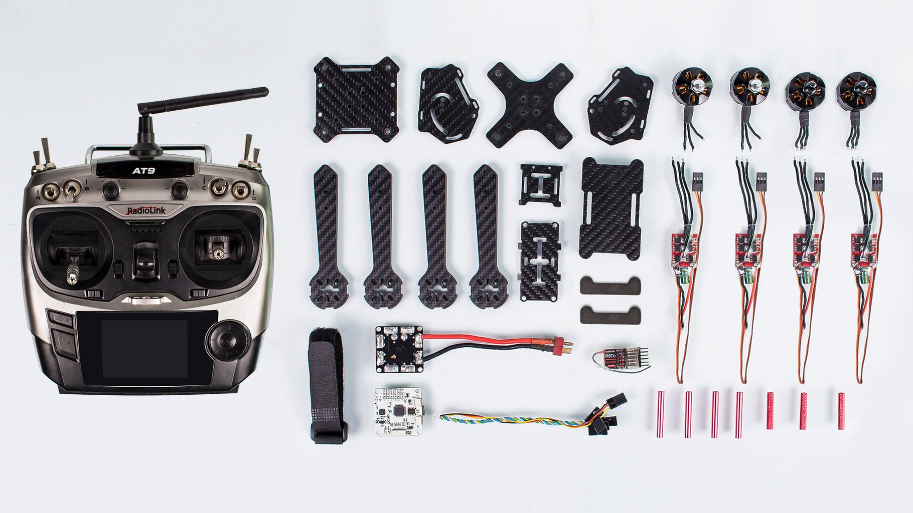
SFX190 frame kit - http://bit.ly/2wzRDE5
4 x EMAX 2204-2300KV motors (2 CW, 2 CCW) - http://bit.ly/2s2hCx6
4 x EMAX 12A (1S-3S) ESCs - http://bit.ly/2t1j6ww
CC3D flight controller - http://bit.ly/2w60CcU
3S-11.1V 25C 1300mAh battery - http://bit.ly/2t2ruLR
RadioLink AT9 radio transmitter
R6DII receiver
Power distribution board - http://bit.ly/2s2wD27
4 x 3-blade 5045 Propellers (2 CW, 2 CCW) - http://bit.ly/2tAQs2x
Heat Shrink Tubing (two types)
Soldering iron - http://bit.ly/2t3fPKx
Heating gun
Scissors
Cutting pliers - http://bit.ly/2trOEMe
Allen wrench - http://bit.ly/2w6nyJd
Tweezers - http://bit.ly/2xeybKb
USB cable
Velcro tape
Step 2: Frame Arms Preparation

- Align the holes of a frame arm to those of a motor, insert the screws into the holes, and tight with the Allen wrench. Mount the rest motors in the same way.
- Cut the thinner type heat shrink tubing into twelve short pieces (4 ESCs in total, each with 3 wires), so that they can well cover the metal parts in later steps.
- Thread the three wires of the ESC through a short tubing. Repeat this operation for the other three ESCs
- Solder the ESCs to the motors separately with the connection randomly as shown, you can exchange later after powering on.
Step 3: Correct Motors Wiring


1. Solder the wiring of ESCs to the Power distribution board (red wire to “+”, and black wire to “-”).
2. Connect the 3P wire on one ESC to pin 3 of receiver (the Throttle channel).
Note: the 3P wire should be insert with the yellow wire on the same side of the receiver’s front side.
3. Then turn on the radio transmitter, pull throttle lever to top.
Note: Here the radio transmitter and receiver have been paired already.
4. Cover the soldering part with the tubing to avoid possible short circuit.
1. Then connect the battery to the power distribution board via cord.
2. Then pull throttle lever to bottom at once.
3. Since motors with white bullet cap are CCW type, while motors with black cap are CW type. Pull the Throttle upward slightly, and you can see the motor starts to spin. Check whether the motor spins in right direction. If a CW motor spins counter-clockwise, exchange any two wires connection between ESCs and motors.
Check and correct all the motors in the same way.
After correction, turn off the radio transmitter, and unsolder the wires on the power distribution board.
Step 4: Organize Wires

1. Heat to tighten the thin tubing with the heating gun.
2. Thread the frame arms through the thick heat shrink tubing separately.
3. Then heat the thick tubing with the heating gun to make sure the ESCs are well-wrapped.
Step 5: Fasten Frame Arms

1. You need to figure out the CW and CCW motor types first: the CCW motors are with white bullet cap, and the CW ones are with black cap.
2. Fasten the frame arms to the bottom plate with screws and nuts.
Note: Make sure the same type motors are on the diagonal line of the frame.
3. Then fasten the arms with screws and single-pass standoffs as shown.
Step 6: Wiring of ESCs and Power Distribution Board

1. Mount the distribution board to the frame with holes aligned with the standoffs.
2. Solder the wiring of ESCs to the Power distribution board (red wire to “+”, and black wire to “-”).
3. Then fasten the board with single-pass standoffs.
Step 7: Wiring of ESCs and Flight Controller


1. Check the flight controller board, the arrow pointing direction will be the frame’s head direction. So when mount the flight controller, make sure the position 2 and position 4 are CCW motors (white bullet cap ones), while position 1 and 3 are CW motors (black bullet ones).
2. Mount the flight controller board to the frame with holes aligned with the standoffs.
3. Then fasten it with nuts.
1. You will see the 1-4 number mark on the light controller board.
2. Cut off the 3P wires of the ESCs.
3. Solder the ESCs’ wires to this area corresponding to the ESCs’ number mark, yellow wires to “S”, red to “+”, and brown to “-”.
Step 8: Mount the Frame Top


1. Insert the screws from one side of the side plate of frame top, and fasten with standoffs on the other side.
2. 3. Then mount the top plate and bottom plate of the frame top.
4. Align the holes of another side plate with that of the standoff, and fasten with screws.
1.2. Thread the screws through the bottom plate of top, and fasten with standoffs.
3. Then mount the frame top to the frame bottom plate, and fasten with screws.
Step 9: Mount the Battery


Thread the Velcro tape through the bottom plate and the nylon spacers, then fasten the battery with the Velcro tape.
Step 10: Connect to Receiver


1. Connect the 3-pin end of the 8-pin cable to pin-1 position (PPM mode) of the receiver, ensure the yellow wire on the same side of the receiver’s front side.
2. Connect the 8-pin end to CC3D Flight Controller as shown.
3. Assembled Frame is shown as above
After propeller mounting, it is shown as above .
Step 11: Flight Controller Configuration

For details of CC3D Flight Controller configuration, please refer to: https://www.sunfounder.com/learn/category/sf250.html
Note: Since the 190 frame is X-shape structure, you should select Generic Quad X in the last step of firmware flashing.


