

Introduction: How to Read Many Switches With One MCU Pin


Have you ever been chugging away at a project(s) and the project keeps growing and growing, while you add more things to it (we call that a Feaping Creaturism)? On a recent project, I was building a frequency meter and added a five function signal generator/frequency synthesizer. I soon wound up with more switches than I had available pins left, so what's a guy to do?
However, I soon had seven more switches on my Funbox (yeah, that's what I called my function generator...I know, I have no creativity) and here's a short instructable showing you how you can do the same. It doesn't require any shift registers or specific IC's. In fact, it doesn't require a microcontroller, either, if discrete semiconductors is how you roll.
Here's one way you can read/manage multiple switches using a single pin on your AVR (or other microcontroller...I've heard there are other microcontrollers besides AVR's, but I can't imagine...). :)
Step 1: The Essentials (not Really)
In order to accomplish this, you'll need a few components. It helps to have a multitude of switches that you have to manage. You'll also need some resistors and either a microcontroller that has ADC (Analog-to-Digital Conversion) or some other way you'd like to indicate that there was a switch activated and which switch it was.
If you wanted you could use a voltage controlled oscillator to indicate this, maybe with some blinken lights, or alternatively, with sound. In this 'ible, I'm going to pretend we're using an AVR, but in your world you can pretend whatever makes you happy. I miss Bob Ross.
Step 2: The Voltage Divider

Essentially, the way we're going to do this is by using a technique and circuit called a voltage divider. Voltage dividers do, as you may have guessed, divide the V,,in,, voltage by some value that you determine. You can divide voltage with several components, including capacitors and inductors, but here I'm going to do it with the good 'ol resistor.
The Idea
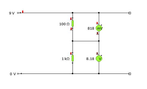
What we are doing is putting two components in series that will cause, each individually, a drop in voltage across the component. Look at the first picture if I'm not making sense. There is a potential difference of 9V from rail to rail. Between 9V and 0V there are two resistors in series. Each of these will experience a voltage drop across itself, depending on the resistance, as you probably recall from V = IR. If you take a voltage measurement between the two resistors, you'll get some value between 9V and 0V, depending on how much voltage has dropped across the first resistor and how much is left to drop over the 2nd resistor, before 0V.
There is a straightforward formula for calculating the voltage drop across a resistor in this situation and it looks like this. Let the voltage over resistor 1 (R1) be V1 and the voltage over resistor two (R2) be V2.
Since I can't use formatting anymore, look at picture 2 below for the formula...
So, in our resistive divider, the Vout voltage can be determined by our formula for V2 (since we'll be referencing GND to 0V).
What does this have to do with having a bunch of switches being detected from one pin? Well, turn the page and I'll show you!
Step 3: Voltage Divider Ladder

In the picture below, I've connected two blocks of switches. The top-most block has two switches, and the bottom-most block has five switches. You can connect your separate toggle, momentary, tactile, etc switches in the same way. The important thing to notice is the resistor that your switch is connected to.
In my example, I've almost doubled the resistance of the next resistor to create a voltage gap that is easy to measure and not mistake for the switch before or after. If you haven't noticed before, look again, and realize that we're back at our old friend the resistive voltage divider. The first resistor, the 10k ohm, is connected to 5V and the 2nd resistor -- the resistor that will determine Vout for SWITCH_ADC pin, is connected to each switch and therefore, each switch is associated with a particular Vout voltage that can be read from the ADC pin connected at SWITCH_ADC.
Next, determine the expected Vout from each switch like so:
Vout = Vin * ( R2 / (R1 + R2) )
for switch one:
Vout = 5V * (500 / (10000 + 500)) = 5*0.048 = 0.24V or 240 mV
for switch two:
Vout = 5V * (2200 / (10000 + 2200)) = 5 * 0.18 = 0.9V or ~900mV
and so on..
Feel free to substitute in your own values for R2 if you only have certain resistors handy...The key thing here is to keep a wide enough gap in voltage between the switches so that any margin of error on the ADC won't put you into the voltage expected from a neighboring switch. I've found the easiest thing to do is to build the divider ladder and put a multimeter/voltmeter on the ADC pin and press each pin and see what values you get. They should be pretty spot on to what you calculate.
Once you have all the expected voltage values from each switch using a particular resistor, then you can have your MCU read the ADC pin and compare that to your known values to determine which switch was pressed. For example, say you have registered an interrupt service routine that will be called whenever there's a detected change on the ADC pin. Inside that ISR, you could read the ADC and compare that value against your switch table. If you're using an 8-bit ADC value, your voltage will be converted into a number between 0 and 255 that corresponds to a voltage between 0V and 5V. This assumes you have your ADC configured this way.
Step 4: Summary
So, now you should know how to be frugal on using GPIO pins for switches. Whenever you are running low on GPIO pins, or hardly have any to start with, or if you realize you're going to be utilizing a bank of switches, the resistive divider is the way to go to save your GPIO pins while still providing a robust mechanism to detect switch access.


