

Introduction: How to Wrap or Upgrade a Brushless Outrunner Motor


A brushless motor uses a pulsed current that alternates between three wires. This fact about them can make it seem confusing about how to make one. There are a few different ways to wrap a brushless outrunner, but I will show you the easiest and most common way. Once you know how to wrap a brushless motor you can change the performance of your motors to have different outputs such as higher torque, higher RPM, and higher tolerances. You have a few different options when wrapping the coils of wire on the stator. More wraps or turns around each pole gives the motor more torque and a lower kv (rpm per volt). More turns will allow the motor to turn a bigger propeller, and fewer turns will limit the torque so it can turn a small prop at high speed. You can use any guage of wire that will fit the motor and you can wrap multipule wires at once for better performance.
Materials:
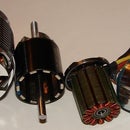
Brushless outrunner motor
(small bell style motors as shown are easiest to work with)
pliers
400 grit sandpaper
enamel coated wire
Step 1: Taking Apart the Motor


Taking apart the motor you want to modify is easy. Start by removing the "C" shaped washer on the back of the motor. Pliers should be able to sqeeze it off. Then pull the outer part of the motor off of the stator (the part that has the coils). Unwind the wire on the motor and be sure to count how many turns are on one of the poles so you know what to change the number to. Some times the wire is glued on, so carefully cut it off.
Step 2: Winding the Motor


There will be at least three main wires that will have to be wound on (usually made of several strands to handle more current). I color coded the wires in the picture, so you can tell them apart. Each wire will be wraped on every third pole. So, on a 12 pole motor as shown below each wire will be warpped around a total of 4 poles. Each wire would be wrapped around 3 poles on a 9 pole motor as shown. Be sure that each coil is wrapped in the same direction on each pole, with the same number of turns , and in the same order.
In the picture the three different colored wires at the bottom go to the ESC.
Looking at the yellow wire, start wrapping on the bottom pole after leaving enough left over wire to go to the ESC. Then, after wrapping the desired number of turns, continue the wire to the pole on the right, then the top, then the left. Do the same for the remaining two wires. Then, you should be left with three loose ends (shown in the picture on the left side of the stator with the bare copper exposed).
Use the fine grit sandpaper to sand off the layer of enamel on the tips of these loose ends until the shiny copper shows. You can either solder them together as shown, or twist them together. This is a Y wiring configuration which will provide the most torque and least kv. The picture where the ends of the wires meet up with the ends of wires of a different color is the most common configuration called Delta. It provides less torque and more speed.
Step 3: Finish
Reassemble the motor and test it out.
For the motors shown in the intro which are about 25-30mm in diameter I got these results:
12 pole motor Y configuration:
4 turns had about 3000+kv
12-16 turns had about 1000-1300kv
20-25 turns had about 700-850kv
9 pole motor Y:
20 turns about 900-1100kv
40 turns about 500 kv

Participated in the
Remote Control Challenge


