

Introduction: How to Install a Furnace Booster Fan on the Cheap


Our master bedroom is always either cold in the winter or hot in the summer. The fact that the builder messed up by installing just one register in the room and the room itself is right above the garage doesn't help either.
Using a digital thermometer I was able to determine that the temperature of the air coming in was half thatof the hottest register in the house (obviously this is for the winter case), and the airflow was barely there.
My solution was to install a booster fan.
The process was not all that complicated and this job can be accomplished by anyone with some basic electrical skills and some tools you can buy at local dollar store.
Was it worth it? The answer is YES. Can it be done better? Yes but not by much. I'm sure some people out there who are familiar with how a furnace works will be able to come up with a better way in regards to how to control the booster fan, like using a pressure switch or choose other outputs on the controller furnace board. In my case, I just went with what worked for me and what I feltwas safe from a functional point of view and liability point of view.
If any good recommendations are made here (and they are easy to implement in my current setup) I will try to include them in the overall design for other users' benefit so feel free to contribute.
I should also mention that this installation deals with electricity and electrical connection which means you might need a permit but most of all YOU NEED TO PUT SAFETY FIRST also, don’t forget your safety goggles.
Step 1: The Fan, the Duct and What Needs to Happen


In this step, I'm going to explain the theory.
So here we go.
The booster fan is installed in line with the existing duct that goes to the register for which you want to increase the air flow. The fan I got has two speeds one for 200cfm and 300cfm.
The power to the fan has to be turned on and off when the furnace is on or off. In my case I used a relay that is energized by the controller board (will get into that later).
There are furnaces that have just one speed for the blower or more than one speed, they may also have separate connections for Heat and Cold (aka A/C). You will need to indentify which connection works best for you.
In my current configuration, the fan only comes on when the Heat is on. Eventually I will use a 2nd relay to power the fan when the A/C is on or maybe a presure switch but given that I can get a relay for $8 vs almost $40 for a pressure switch I think I'll go with a relay.
Optional you can install a regular switch to disable the fan in case it becomes noise later on, etc. It's just good to have it and it's not going to cost you more than $5 to do it anyway.
So in a nut shell, here is how it works, the furnace comes on and the inducer motor kicks in, after a set delay the blower motor starts up, as soon as that happens, the relay coil is energized and switches on the power to the fan. When the blower is turned off by the controller board the relay will also switch off the power to the fan.
Step 2: The Parts and Tools


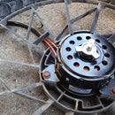
Well, obviously, you will need a booster fan. I got mine for $30 (on sale) from Pricess Auto
www.princessauto.com/farm/
I got the relay from Eastern Refrigeration for about $8
www.easternref.ca
The rest of the stuff I already had it or got from Home Depot.
Here's what you'll need (prices are approximate):
* 15A 14-2 (white) wire - you don't need to buy a spool, you can by a "pack" or just ask them to cut it for you. I already had a spool so, sorry, no price.
* Armored cable. I need about 15ft - around $19
* 16 gauge conductor black and white, 3 feet each.
* Junction boxes - see pictures for more info. They are usually around $3-4. You will need one to connect the fan. Most likely your local code will require you to have all non low voltage connections made in a junction box. I used a shallow receptacle box for the connection at the fan end and a regular one for the "disable/enable" switch. For the connection in the furnace I used a square box just to have more room. Next time I will look for a bigger box that will accommodate 2 relays. As a side note, all connections have to be accessible in case there is an electrical problem.This means that if you ever finish your basement and your junction box will be hidden by drywall, you have to cut the drywall and have some sort of access door (panel door). This is not only good practice but it's also electrical code.
* Disconnects
* Marrettes for wire connections pack of 15 $2 (aka, wire nuts or wire connectors)
* Electrician's tape $.50
* Wire staples
* Wire clamp
* Zip ties
* Switch (optional) $.50-2.50
* Aluminum tape (optional)
* Shrink tube (optional)
* 3" wood screws
* 1/2" bolt and nut to secure the box to the furnace (optional)
Tools
* Hammer
* Drill
* Snips
* Knife
* Drill bits and preferably a step bit
* Crimp tool
* Wire cutters
* Safety goggles
* Meter (optional but you will need it if you can't find the terminals on the controller board)
Step 3: The Relay Connection
For those not familiar with relays, here is a quick intro.
A relay is nothing more than a switch that is activated by applying power to two terminals connected to the coil inside the relay (aka energizing the coil). When the coil is energized, it acts like a magnet (this is how all electromagnets work and a relay is no different). The electromagnetic field attracts the contact blade inside the relay; this is pretty much the equivalent of flipping the switch on.
When there is no power to the coil, the contact blade is in itsnormal position. The word normal has not been chosen at random.
Relays have two kinds of contacts NC and NO. The NC stands for Normally Closed and NO stands for Normally Open. The logic is simple, when the contact blade is in its normal (non-powered) position thecontact can be NC or NO. There are relays that have only one kind of contact (NC or NO) or both in which case you pick the connection that suits your application. An NC connection means that the switch is on when there is no power to the coil and the opposite is NO. One easy way to remember which one's which is like this: when a switch in a circuit is closed it means that it closes the circuit just like a complete circle (you can go around that circle forever, closed circuit), when it's open it's like the wires are up in the air and the current has nowhere to go (somebody took an eraser to our circle and now the circle is broken, sooner or later you will hit an end).
All relays have some specifications (usually, printed right on the case): coil voltage, contacts rating (voltage and current) and post (terminal) diagram.
Coil voltage shows you what kind of power is needed to energize the relay. This could be 120V AV, 240V AC, 12V DC, 24V DC, etc. In this instructable we will be using a 120V AC relay.
The contacts rating tells you what the relay can handle. If it says 120V/10A it means you can use it in a circuit that will switch on and off a load that uses no more than 120V at a pick current of 10A. Can you use this to switch a 12V/10mA load? Of course but why would you use a higher rated relay like that when you could use a smaller and cheaper one. The point here is: do not use a relay that can't handle the load.
Lucky for us, the booster fan is not a big load. I used a big relay only because I found it for $8.
Step 4: Installing the Fan in the Duct


This can be tricky, especially if the duct is behind the ceiling. In my case, the basement is not finished and I had access to the duct but still I had to have help to remove a section of the duct.
First thing you need to do is to identify the correct duct. It would be a real pain in the rear side to install this in the wrong duct.
Start by removing the aluminum tape if you have it. The easiest way to cut it is to get a piece of wire (I used some MIG welding wire) and make a knot in it, wrap it around the duct and in a back and forth motion "cut" the aluminum tape on top of the duct (where you don't have access to cut it with a knife), the knot in the wire will tear the tape. For the bottom, just use a knife. You can get a better idea of what I'm talking about if you look at the picture below.
Locate the screws that hold the duct segments together and loosen the segment and work one of them out.
Once you have one out, open it up by undoing the seam, rest the fan on it and make a mark from the clean edge of the duct to the point on the fan where it just starts to get "wrinkled" (that part will go inside the duct after you cut it to the new length) - see the picture.
At this point you need to figure out if the fan should go first into the duct that hasn't been removed or the one you just cut. This decision is based on accessibility.
You can drill some pilot holes for the screws or just see if you can actually make the self tapping screws go in without the pilot hole.
Step 5: Running the Wire to the Furnace
Find a place where you want to enable/disable switch and run the 14-2 cable to the fan.
Pull the cable in the connection box, about 4", remove the plastic sheathing and strip the end of the wires about 1/2". Secure the cable by tightening the clamp in the box.
Do the same for the fan wires. Twist together the stripped ends of common wire with the white wire and then turning clockwise twist the marrette on the ends.
Connect the black wire to yellow or red following the procedure above.
The bare wire and the ground wire go together and they are attached to the box. You can either connect them directly to the box or use a "pig tail" bare wire with one end connected to the box and the other to the bare wire coming from the furnace and the ground coming from the fan.
Note:
The black wire is always the live wire (by code). One way to remember which one is live is that death is black and if you are messing around with a live wire the black death is just around the corner.
If you ever need to use a different color wire just wrap a piece of black electrician's tape on it to indicate that the wire is the live one.
Pull the 14-2 in the switch box and prep it for hooking it up to the switch by removing the plastic sheathing and striping the ends.
Staple the cable once you're done with the connections.
Step 6: Moving on to the Controller


THINK SAFETY FIRST
Before you do anything else, turn the furnace power off. Most likely your furnace has a main switch, make sure it is in the off position.
Remove the furnace cover.
Locate the connection diagram on the inside of the cover. I will talk about it in a second. For now I want to focus on the overall connection diagram for the booster fan.
If you take a look at the fan diagram below you will notice some of the parts I've been talking about, booster fan, relay, blower motor, etc.
One thing to keep in mind is that all the info here refers to MY furnace, your connection diagram might be different but the theory behind all this is the same.
OK, let's dissect this diagram.
The dots represent connection points in our circuit, they can be on the controller board, in a junction box, etc. More wires can go to those points, I've shown only the ones we care about.
Let's start with the blower motor. Like I mentioned before, I wanted the relay to be energized when the blower motor was on. In this case, the HUM terminal has 120V when the motor is on HEAT, a separate circuit on the board takes care of the motor when A/C is used.
To cover the A/C scenario, I will add a separate relay connected to Common and A/C. The switch in the relay will be in parallel with the COLD switch. When energized, this relay will act just like the existing relay.
So this covers how the relay gets triggered.
Now, once the relay closes the circuit (again, closing the circuit means current can flow through it) power can be sent to the booster fan (assuming the enable/disable switch is also closing the circuit). There are two thingsyou need to pay attention to here:
- power is sourced from L1
- the common contact point is really a common contact point.
You should be able to determine where Common and L1 (or whatever it’s called on your diagram) by examining the furnace connection diagram or using a volt meter and turning on the furnace (up the heat on your thermostat to make sure the furnace comes on). Make sure your L1 is not powered when the furnace is off.
In my case I had to create a Y cable for the L1 connection. There were no terminals available on the board so using some 167 gauge conductor I crimped one end with a female disconnect, soldered the other end to two other wires and using a piece of shrinking tube I insulated the connection (you can use electrician's tape). One of the two ends was crimped with male disconnect (so the disconnect that was hooked up to the board originally can be connected again) and the other end was crimped with a female disconnect for the terminals on the relay.
The rest of the connections were made with white or black 16 gauge wire using female disconnects.
This sounds complicated but once you get going and follow the connections you will get it.
The pictures below will help a lot to understand what needs to happen.
I should mention here that there is probably an easier way to turn the booster fan on but I don't know enough about how a furnace should work. A pressure switch will work but I'm happy with the relay solution even though I have to modify it later for A/C.
Step 7: Hook Ups and Testing


Using a large drill bit, drill a hole in the side of the furnace where the armored cable will come through.
A step drill bit will come in handy but you can do this with a dremel tool. I highly recommend the step bit. You can probably find one for less than $15, don't go nuts on specially coated step bits, just get something to finish the job.
At this point, it is a matter of hooking everything up.
Identify the connection points on the board, run the wires to the relay and connect everything up.
Check, double check and triple check your connection. You don't want to fry the controller board just because you made a "small" mistake like hooking L1 to Common in effect creating ashort.
For all other connection not using a disconnect terminal just usethe striped wire end and marrette technique explained in Step 5.
I should touch on how to cut the armor. Look at the picture. You will see that I bent the cable and as a result, the armor just "snapped" out. Using wire cutters (side/diagonal cutters) cut the metal strip. Be careful not to cut the wires or the insulation. This sounds complicated but believe me, once you bend the cable you will see what needs to be done.
After you cut the armor, trim the cut end so it doesn't slice the insulation and pull it out.
Run the end in the junction box and secure it with the clamp.
If you are not installing an enable/disable switch then you don't need the armored cable. In this case the 14-2 will go into the box.
If you are installing the switch then run the other end of the armored cable to the box where the switch is and make the necessary connections. Remember, the black wire will be connected to the switch, the white one will be connected to the 14-2 cable and the bare wires will be connected together and hooked up to box.
The pictures below will show where things are and what you need to do.
TESTING
When all connections are done, restore power to the furnace, crank up the heat on the thermostat, if you used a enable/disable switch make sure it is in the ON position and either push the interlock switch or tape it (don't forget to remove the tape when done).
At this point, after the blower motor kicks in you should hear the relay being energized (one click). Go to the register and inspect for higher air flow. At the thermostat either turn down the setting or just use the OFF position to turn off the furnace, when everything is off (there will be a delay) inspect the register again to make sure the fan is not on anymore.
Step 8: Wrap Up and Final Thoughts
If everything checks out OK, put the covers back on the furnace, junction box(s) and switches.
Wrap aluminum tape over the joints.
Final thoughts
-- Performance --
The airflow has increased by about 100% and the temperature by 30-40%, which really made a difference in our case.
You can hear the fan working so this is not silent solution but the noise is not bad plus it gives you an indication that the fan is not stuck.
The humming generated by the fan is actually therapeutic (at least for me it is).
-- Other thoughts --
Always put safety first, turn off power, use safety goggles, insulate exposed wires, etc.
Do not use a switch from the Dollar store, for about the same preice you can buy one from Home Depot or Lowes. Mine was bad and I had to do some troubleshooting. As a matter of fact, the instructions for the Dollar Store switch said to connect the black and white wires to the switch terminals which means to close the circuit between the live and neutral wires in effect creating a short-circuit, so be careful there.
Make sure all wires/connections are insulated properly.
If you are not comfortable working with electricity then don't do it, ask a friend or bring in an electrician to help you. electricity can and will kill you given the right circumstances.
Enjoy your new booster fan.


